| Home |
| Email John |
| Created 08/13/09 Last update 02/27/2011 |
A 1kW Royer Induction Heater
Update 03/22/2010 - Our commercial web site, http://www.fluxeon.com is now up and running. Still in a preliminary stage so don't be too hard on us. That is the place to go to buy kits and complete induction heaters.
Update 03/11/2010 - Ferrite Transformer Winding and Performance Click here
Update 03/06/2010 - Ferrite cores are now in stock. Click here for more info plus important Safety Warnings.
Update 02/22/10 - While running my heater at significantly higher power than 1200 watts, I had the trace on the PCB that leads from connection W2 down to the terminal of C1 overheat to the point that the trace lifted from the board. Therefore I have revised the board layout to version 1.1 which has much wider traces for all conductors that handle the resonant current. Both the file and the board itself are marked with version 1.1. That is the file that is hyperlinked below. If you've downloaded Vers 1.0, I highly suggest getting 1.1 before having a board made.
The Royer power oscillator-based induction heater is an incredibly simple yet very powerful design. Though the Royer architecture is ubiquitous (your laptop's backlight driver probably uses one), there seems to be very little information on the net about how the architecture works. I'm going to address that problem and present a very simple but very powerful induction heater based on the architecture.
The Basics
 The
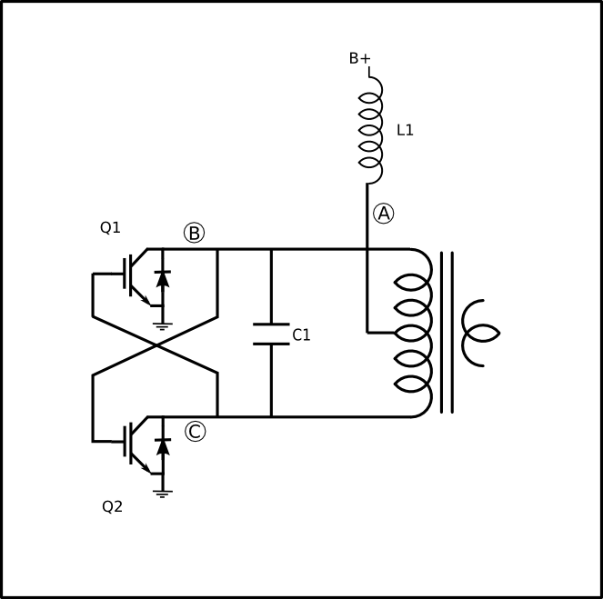
diagram shows the basic Royer oscillator. It consists of a transformer
with a center-tapped primary, a choke labeled L1, two semiconductors
(here shown as IGBTs though they could just as well be FETs or bipolar
transistors) labeled Q1 and Q2, a resonating capacitor labeled
C1 and cross-coupled feedback illustrated by the crossed lines. In
a real world oscillator there will be other components such as steering
diodes, bias resistors and so on but this simplified drawing shows all that
is necessary for the basic Royer.
The
diagram shows the basic Royer oscillator. It consists of a transformer
with a center-tapped primary, a choke labeled L1, two semiconductors
(here shown as IGBTs though they could just as well be FETs or bipolar
transistors) labeled Q1 and Q2, a resonating capacitor labeled
C1 and cross-coupled feedback illustrated by the crossed lines. In
a real world oscillator there will be other components such as steering
diodes, bias resistors and so on but this simplified drawing shows all that
is necessary for the basic Royer.
Operation is as follows. When power is applied at B+, DC current flows through the two sides of the transformer primary and on to the transistors' collectors. At the same time the voltage appears on both gates and starts to turn the transistors on. One transistor is invariably a little faster than the other and will turn on more. The added current flowing in that side of the transformer does two things. One, it robs drive from the other transistor. Two, the auto-transformer action impresses a positive voltage on the conducting transistor, turning it hard on.
The current would continue to increase until the transformer saturated were it not for C1, the resonating capacitor. The capacitor causes the voltage across the primary to first rise and then fall in a standard sine wave pattern. Let's say that Q1 turned on first. The voltage at point B will be clamped to near ground while the voltage at point C rises to a peak and then falls as the tank formed by the capacitor and transformer primary oscillator through one half cycle.
As the voltage at point C passes through zero, the drive to transistor Q1 gate is removed, turning it off. That allows the voltage at point B to start rising and in turn, turn Q2 on. Q2 clamps the voltage at point C to near zero, ensuring that transistor Q1 remains off. Then the same sequence as described for Q1 above occurs and the oscillator completes one cycle.
The oscillator runs at the frequency determined by the inductance of the transformer primary, the capacitor value and to a lesser extent, the load applied to the secondary. Generally, a good place to start to determine the operating frequency is the familiar formula for resonance,
F = 1/ 2*pi*sqrt(LC).
The Royer heater that I present here runs at about 100 kHz, depending on the load.
Waveforms
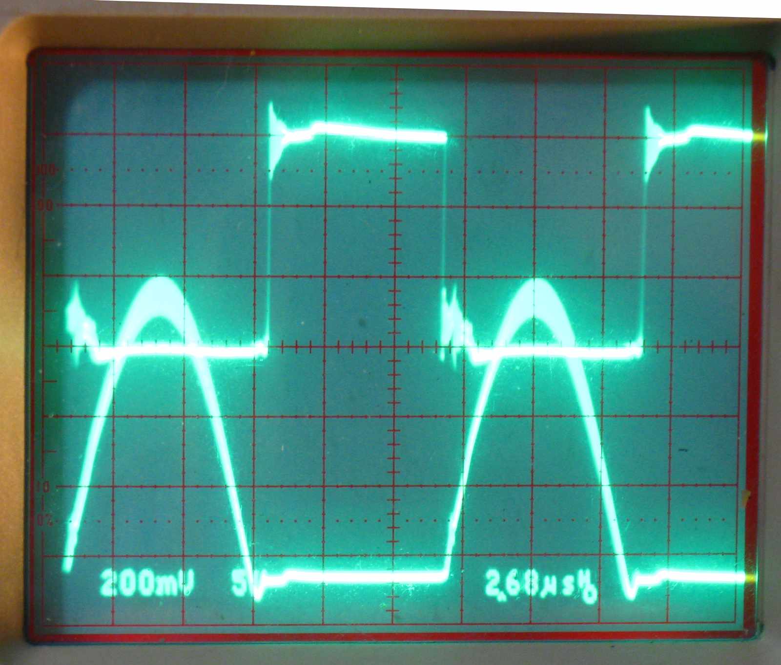 This
scope shot shows two important traces. The top trace is the gate drive
of Q1 while the bottom trace is the voltage at point B.
As you can see, when the gate drive of Q1 is on, the voltage at point
B is clamped to near ground. When the half-cycle is complete
and the gate drive turns on, the voltage at point B soars. This
is the signal that drive the gate of Q2.
This
scope shot shows two important traces. The top trace is the gate drive
of Q1 while the bottom trace is the voltage at point B.
As you can see, when the gate drive of Q1 is on, the voltage at point
B is clamped to near ground. When the half-cycle is complete
and the gate drive turns on, the voltage at point B soars. This
is the signal that drive the gate of Q2.
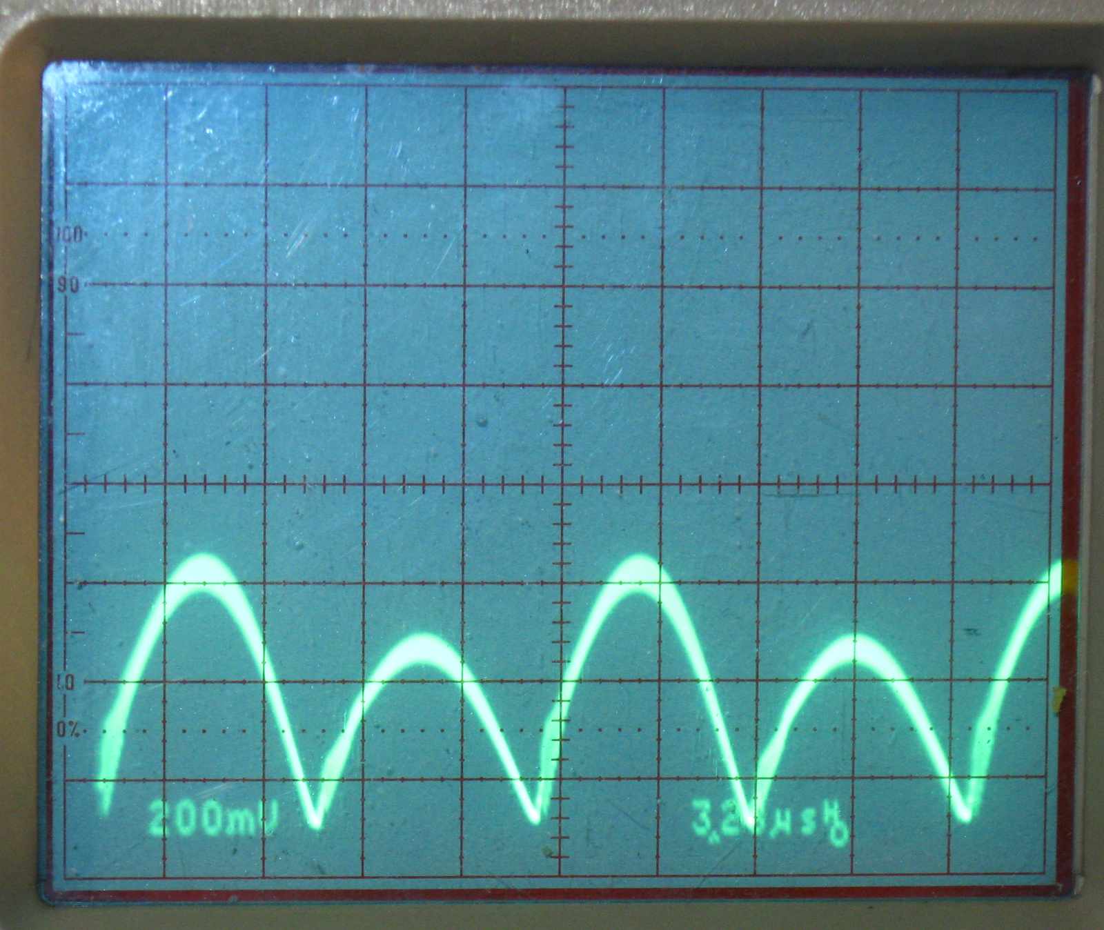 This
photo shows the waveform at point A. Here you can see both
half-cycles happening. They should be of equal amplitude but in every
Royer oscillator that I've ever built, one side is slightly larger than the
other. I have no explanation.
This
photo shows the waveform at point A. Here you can see both
half-cycles happening. They should be of equal amplitude but in every
Royer oscillator that I've ever built, one side is slightly larger than the
other. I have no explanation.
This illustrates another important point. This is a Current Fed Oscillator. This is a term that is used frequently in the induction heating literature. What it means is that because of the inductor, the current flowing through the transformer and FETs is practically constant (a square wave) while the voltage varies as a sinusoid.
The other induction heater that I present on this site, the half bridge secondary resonant one, is a Voltage Fed Oscillator. In that instance, the current through the coil varies as a sinusoid while the voltage is constant for each half cycle.
The Real Thing
A real world Royer oscillator is somewhat more complex. First, the gates can't be driven directly because the voltage across the transformer primary is much higher than the gate breakdown voltage. In fact, the voltage appearing on each transistor's collector is approximately pi*applied voltage. We use a clever trick with diodes to get around this problem.
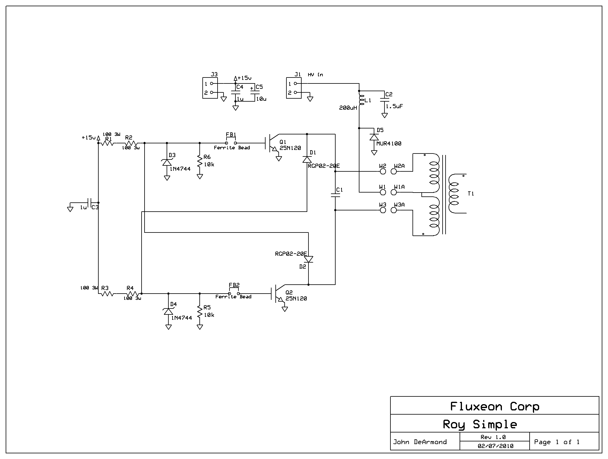 Here is the schematic of an actual Royer induction heater. It
doesn't differ that much from our basic theoretical model. The
critical differences are Diodes D1 and D2 and resistors R1 through
R4.
Here is the schematic of an actual Royer induction heater. It
doesn't differ that much from our basic theoretical model. The
critical differences are Diodes D1 and D2 and resistors R1 through
R4.
Let's look at one gate trigger chain, D1 and R3 and R4. When transistor Q1 is turned on, the circuit works just as described above. The gate of Q2 is held near ground (a diode's drop plus the IGBT's drop to be accurate) and thus turned off. Now let's consider what happens when that half cycle is finished, Q1 turns off and the collector voltage starts to rise. When the heater is operated from rectified line voltage, as this one is, the collector voltage will rise to almost 700 volts. But! That 700 volts is blocked from getting to the gate by diode D1. The specified diode is a fast high voltage diode with a 2000 volt PIV rating. Thus the only voltage that can reach the gates is the 15 volts supplied through R3 and R4. I use two resistors in series to spread out the dissipation and therefore avoid high cost non-inductive high wattage resistors.
There are several other components in the Q1 gate chain. D3, the 15 volt Zener diode protects the gate in two ways. One, it prevents the positive signal from ever exceeding 15 volts. Two, it prevents the gate from ever going more than 0.7 volts negative. This is important, as there is significant ringing on this line otherwise. R6, the 10k resistor protects the gate from floating transients that might otherwise accumulate on the high impedance gate. Finally, the ferrite bead, FB1 suppresses a high frequency parasitic oscillation that sometimes happens with the high gain IGBT specified.
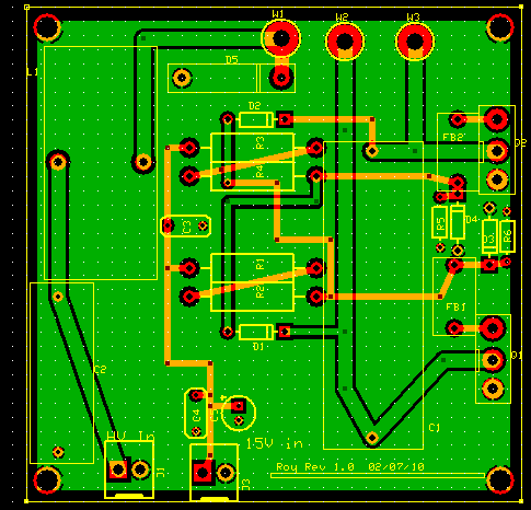
Here is the board layout. The actual board in ExpressPCB format is here. As with the other induction heater, you may use this board for your own personal use. If you want to use this design or board for commercial purposes including group buys, then you must contact us for permission. Email addresses at the left. If you just want a board, then contact Garett and see what we have in stock.
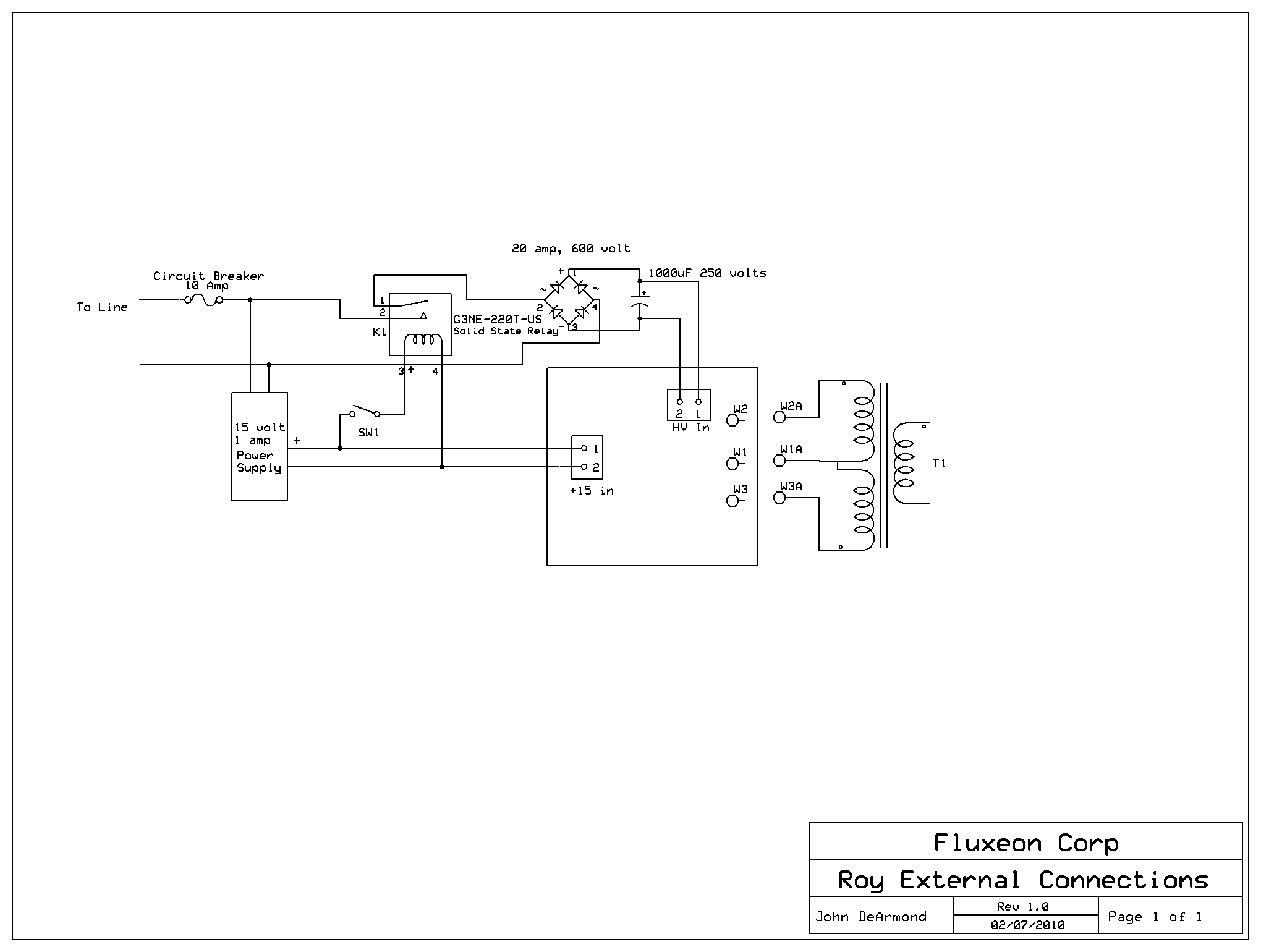
Here is the external wiring schematic. Simple, huh?
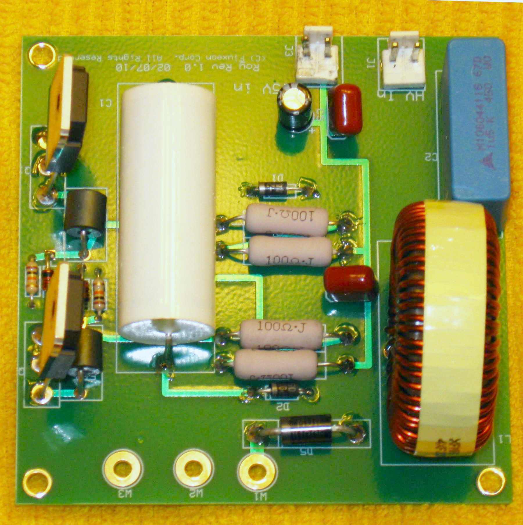
Here is a photo of the completed PCB. Very simple but very effective.
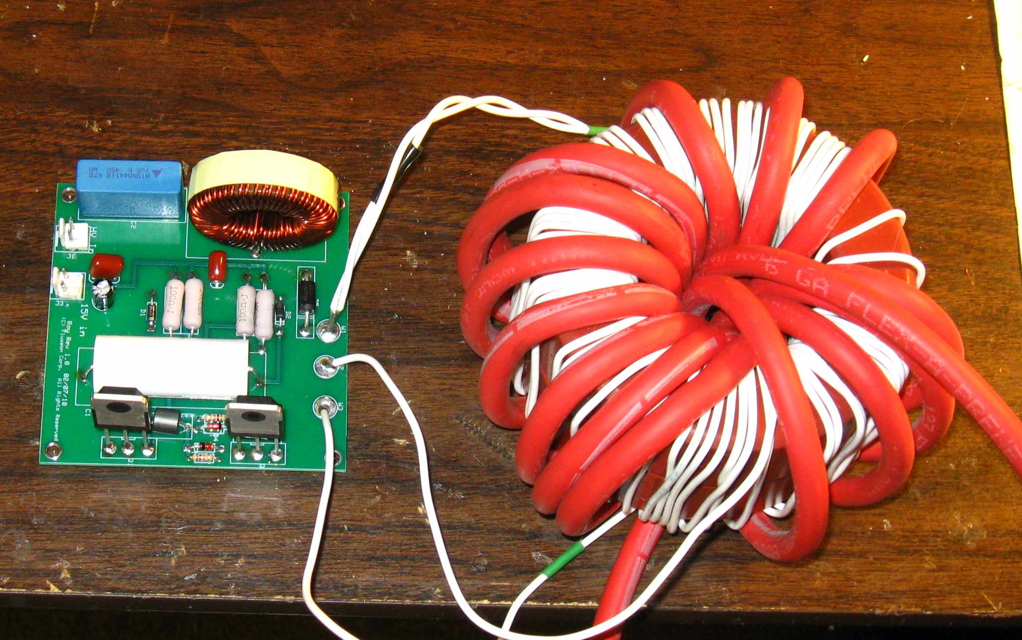
The circuit board connected to the large transformer.
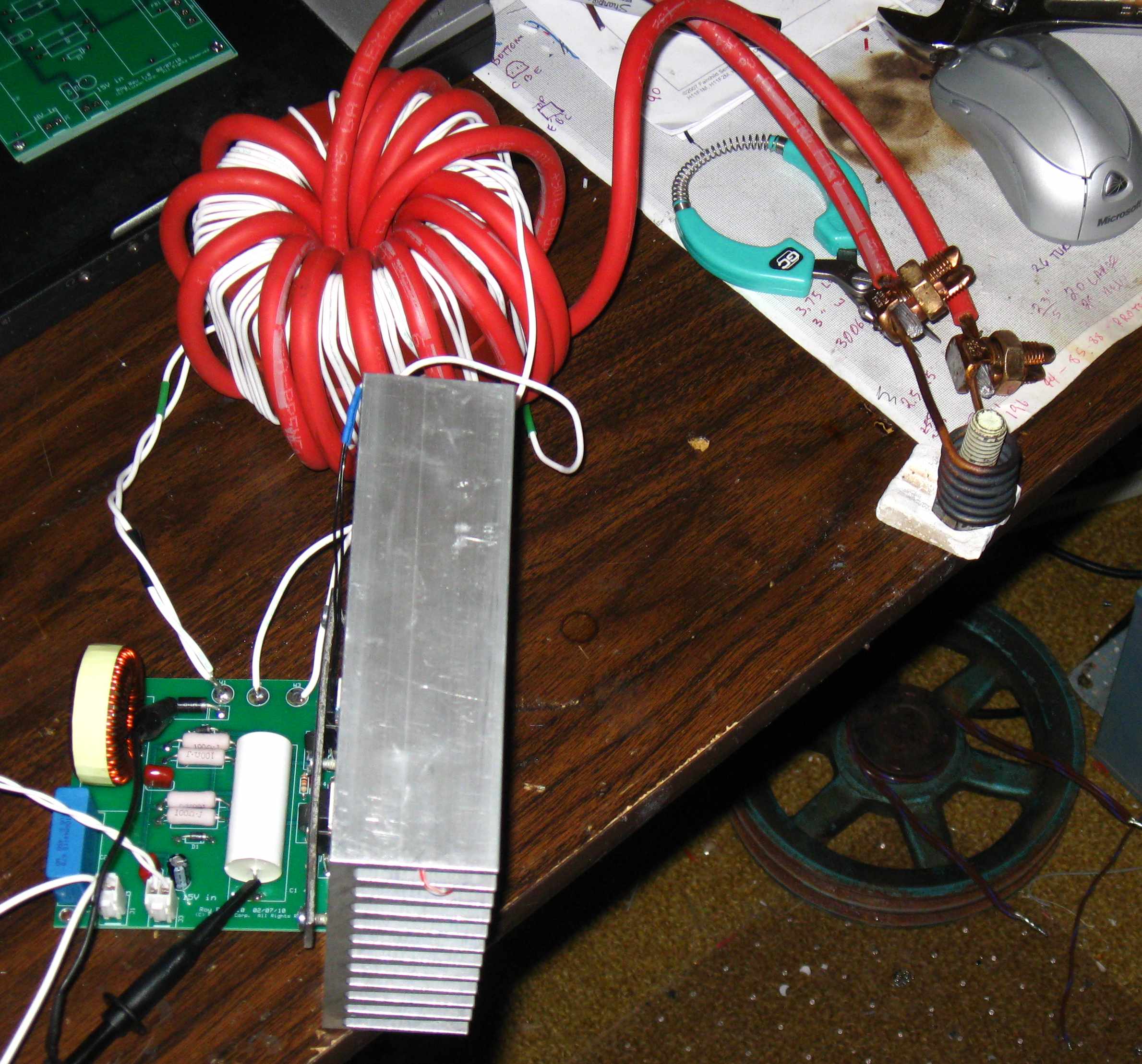
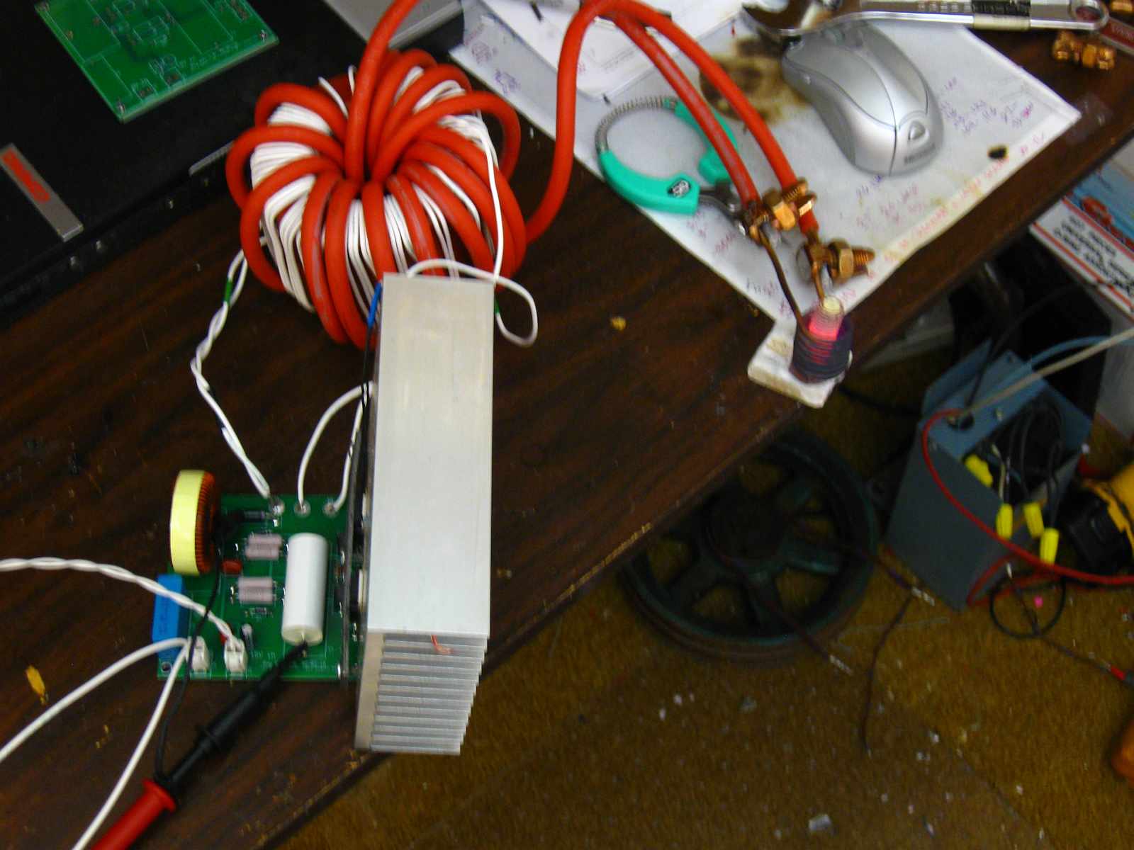 Here is a photo of the actual heater wired up on the bench and connected
to a work coil. In this photo he is putting about 800 watts into that
1/2" bolt.
Here is a photo of the actual heater wired up on the bench and connected
to a work coil. In this photo he is putting about 800 watts into that
1/2" bolt.
Transformer
![]() Unlike
the other heater, this heater requires a high frequency transformer.
This transformer can take many forms, depending on the power level and duty
cycle that you plan on. The photo shows a large transformer wound on
powdered iron cores and is rated for continuous duty. The red cable is
#6 welding wire! For short duty cycle work, one can use four Amidon
#T225-3 cores stacked together. The primary is 40 turns center-tapped
of #12 wire and the secondary is 6 turns of the largest wire that will fit
in the core. Probably #8 to #10. Note that this core will
overheat in just a couple of minutes so it is strictly for short duty cycle
use only.
Unlike
the other heater, this heater requires a high frequency transformer.
This transformer can take many forms, depending on the power level and duty
cycle that you plan on. The photo shows a large transformer wound on
powdered iron cores and is rated for continuous duty. The red cable is
#6 welding wire! For short duty cycle work, one can use four Amidon
#T225-3 cores stacked together. The primary is 40 turns center-tapped
of #12 wire and the secondary is 6 turns of the largest wire that will fit
in the core. Probably #8 to #10. Note that this core will
overheat in just a couple of minutes so it is strictly for short duty cycle
use only.
The large cores are not available on the market in small quantities. However, we will sell them to interested parties, either as bare cores or as wound transformers. Contact Garett for availability and pricing.
We are investigating a much smaller ferrite core for this application but as of this writing, I don't have anything to report.
Use
Unlike the other heater, this heater is only semi-resonant and can use any sort of work coil including a straight piece of wire for heating long narrow parts. Also unlike the other heater, this one requires tight coupling between the work coil and the work. It would be typical to wrap with work with a work coil.
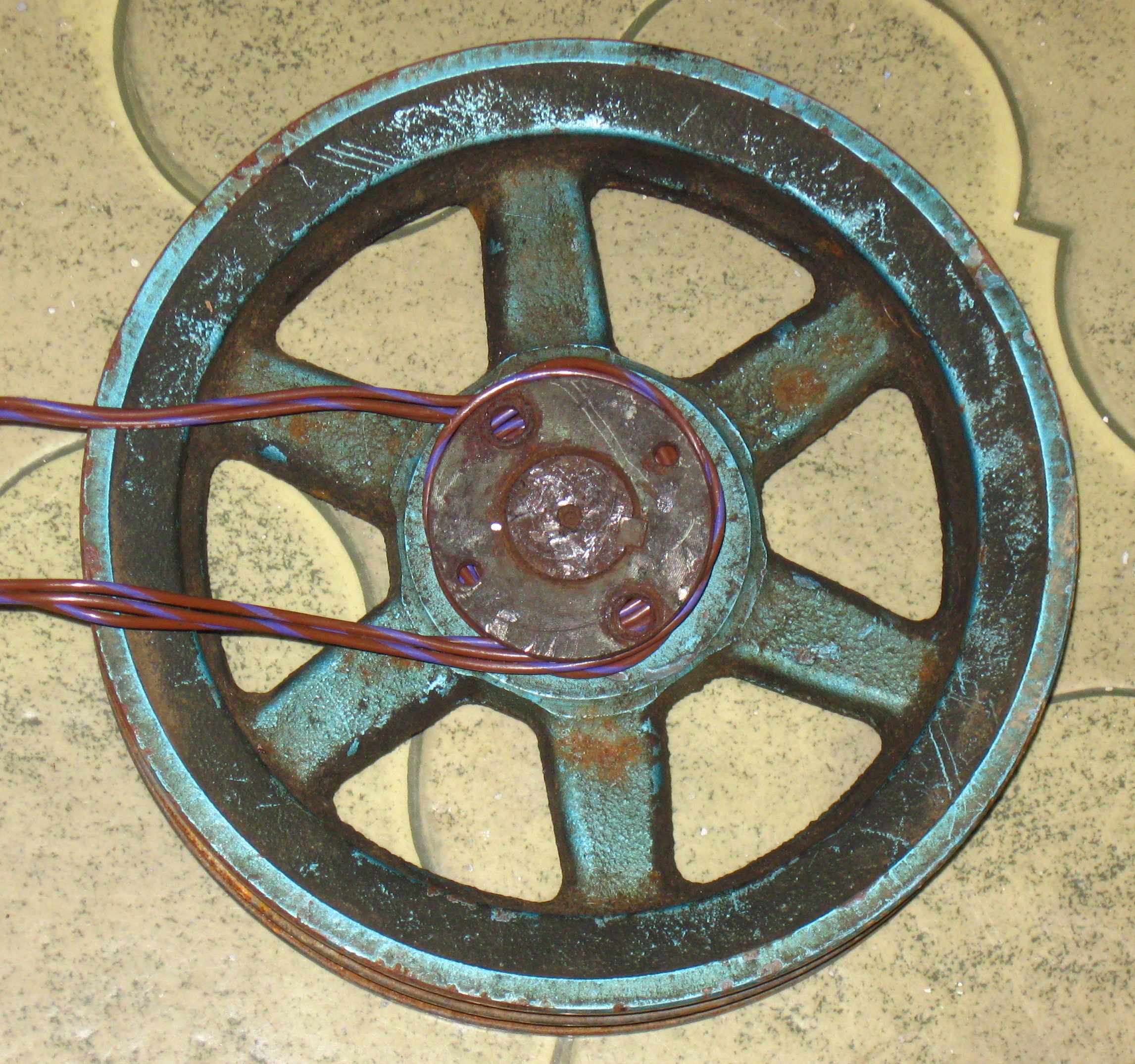 Say
you need to heat a pulley hub to get it loose from a rusted shaft.
Simply wrap several turns of wire around the hub and connect it to the
heater. Turn on the heater and in seconds the part will be heated to
several hundred degrees.
Say
you need to heat a pulley hub to get it loose from a rusted shaft.
Simply wrap several turns of wire around the hub and connect it to the
heater. Turn on the heater and in seconds the part will be heated to
several hundred degrees.
In this photo I show several strands of 16 gauge teflon-covered wire. Just what I happened to have on hand. Any sort of wire will do. 10 gauge or larger is recommended for most jobs.
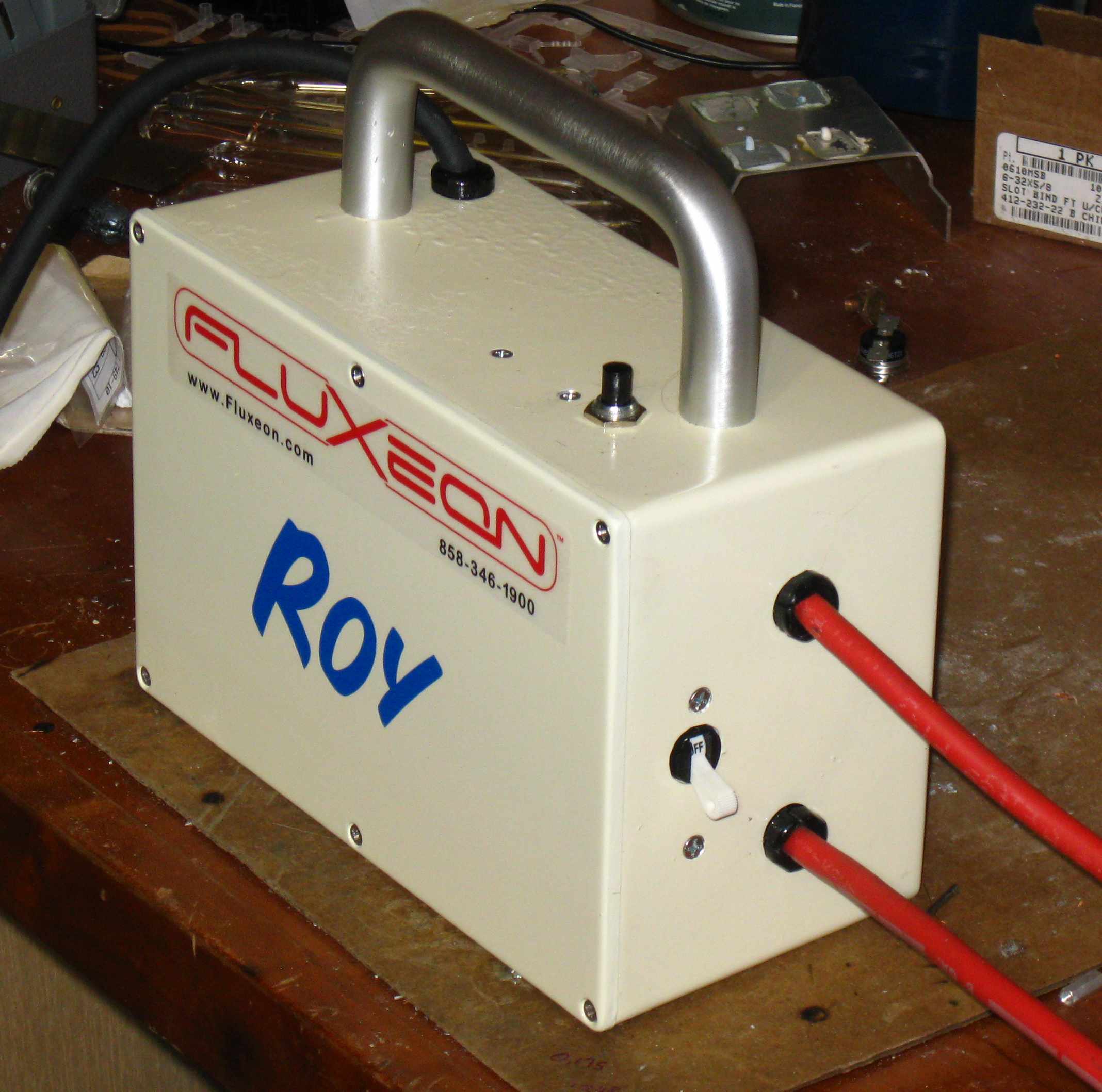
 This
photo shows how well Roy works. After 1 minute of heating, the hub of
this pulley is at 353 deg F. To do this with a torch would take
several minutes and with the grease and dirt on the pulley, would leave a
burned, blackened and scorched mess. Roy did this heating with no
smoke and no soot. Not even any scorched paint.
This
photo shows how well Roy works. After 1 minute of heating, the hub of
this pulley is at 353 deg F. To do this with a torch would take
several minutes and with the grease and dirt on the pulley, would leave a
burned, blackened and scorched mess. Roy did this heating with no
smoke and no soot. Not even any scorched paint.
BTW, the real product will NOT use those split bolt connectors! I have designed a custom connector that attaches to the work coil with a simple thumb nut but those are still at the machine shop.
Protection
The amount of power delivered to the load is determined by the transformer ratio and the number of turns wrapped around the work. It is easily possible to exceed the ratings of a 20 amp branch circuit and even burn out the transistors by overloading the unit. While our commercial version has load limiting, this one does not. Therefore it is imperative that circuit protection be used. We recommend a high speed magnetic circuit breaker such as that made by Heineman or a fast acting fuse. The Heinemann trip profile is #64. The circuit breaker is available from us as well as other distributors. A household circuit breaker is NOT fast enough to protect the transistors. Be Warned: You will smoke transistors if you ignore this paragraph.
If you choose to use a fuse, you must use a 250 volt 10 amp fast action ceramic fuse. Do not use an automotive fuse!!! One of my customers did and ended up damaging the board. An automotive fuse continues to conduct for several cycles through the arc created in the glass tube. It allows through enough current to burn the traces off the board if there is a short in the FETs. I strongly recommend against fuses. Not only are they expensive but they're not nearly as precise as the specified circuit breaker. The specified breaker conducts 10 amps, trips at 12.5 amps and its let-through on a short is limited and short, only a cycle or two.
Commercial Unit
Within a month of this writing we will have a commercial version of this unit available for sale. It includes several features not included in the simple unit presented here. Features include protection against overload, a handy package that easily fits inside machines and an extended duty cycle. Visit Fluxeon.com for information as it develops.
Update 03/06/2010 -
 We
now have a very nice Magnetics
ferrite core and coil forms in stock. This core is good for >1500 watts in
Royer oscillator service. This is the core that our commercial product
is built around. Contact Garett for info on purchasing.
We
now have a very nice Magnetics
ferrite core and coil forms in stock. This core is good for >1500 watts in
Royer oscillator service. This is the core that our commercial product
is built around. Contact Garett for info on purchasing.
- WARNING - An issue has arisen from a user. He
smoked his transistors by connecting the high voltage to the board before
connecting the +15 volts. The board must NEVER have high
voltage applied when there is no +15 volts present. It is 100%
guaranteed to smoke the transistors. Similarly, it is not
possible to control the heater by turning the +15 volts on and off.
Again, smoked transistors will result. The only way to control this
simple heater is to turn the high voltage on and off. I recommend
using a zero crossing solid state relay to avoid the inrush surge to the
bridge rectifier and filter capacitor.
- WARNING - I made a layout error on the rev 1.1
and below boards that results in the mounting holes being connected to
the "ground plane". This "ground", like all the grounds in the
circuit are actually at 60 volts above neutral and earth ground.
If you mount the board with metal hardware, whatever you mount it to
will become hot or if it is grounded, a short will result. I have
corrected this problem in the current rev board available for download
above.
- Based on the experience from several boards, I have found that the
ferrite beads shown on the schematic in the IGBT gate leads are not
necessary. I had parasitics on the breadboarded version of this
heater but the PCB version is clean and sharp. If you use the
current board layout then either jumper across the spots where the beads
are shown or use the ExpressPCB to edit out the bead locations.
- I recommend using a zero crossing solid state relay to control this
heater. The one that I'm using in our product is Omron model
G3NE-220T-US-DC12, available from
Mouser Electronics. This relay should be wired so that it gets
its "coil" voltage from the same 15 volt supply that powers the board.
That way high voltage can never be applied unless the +15 volts is
available.
Note that like all solid state relays, this one has a small amount of "off" leakage. Therefore the heater will have a small amount of high voltage on it even when the relay is off. Therefore don't touch the board until the power source is removed.
Update 03/11/2010 Transformer Winding
In this section I show you how to wind a transformer using the Magnetics core. In contrast to the toroidal transformer, this type of transformer is wound on a coil form and then the core is inserted into the form and fastened in place. Let's get started. (Note: All materials mentioned in this article are available from Fluxeon.)
![]()
This photo shows the Vulcanized Fiber coil form and the start of the first layer of the primary winding. We're winding the primary out of 11 gauge equivalent Litz wire. The Litz wire is bound to the core using thick superglue and an accelerator The spot of superglue can be seen under the wire.
![]()
In this photo I have wound the first half of the primary - 14 turns. After the photo was taken, the turns were tightened up and pressed close together. Then another daub of superglue is used to secure the finish wire end.
![]()
Here we have pulled a loop of wire out that forms the center-tap - I recommend about a foot - and covered the first layer of turns with a layer of mylar/Nomex insulating paper. It is wrapped tightly around the first layer and secured in place with super glue. Then, making sure that the winding is going in the same direction, the wire is bonded to the paper.
![]()
Here the second layer is finished and the end is secured in place with superglue. The end is on the left side of this photo.
![]()
Here the inter-winding insulating paper is applied. Because this separates the high voltage primary from the low voltage secondary, it is applied two layers thick and secured with super glue.
![]()
This is a slightly larger photo showing the whole coil assembly including the leads. The loop on the left side will be twisted together to form one heavy center-tap connection.
![]() Solder
dipping the ends of the Litz wire. Most all Litz wire comes with
"solder through" insulation. That is, the insulation melts and/or
evaporates at bout 700 deg F. in this photo I'm using an inexpensive
Chinese made solder pot. Before I got the pot, I did my solder dipping
using a cast iron muffin tin heated on the kitchen stove. The solder
should be at least 700 degrees before dipping. Also, before dipping
apply some liquid soldering flux. This helps displace the insulation
and makes the solder wet the wire better.
Solder
dipping the ends of the Litz wire. Most all Litz wire comes with
"solder through" insulation. That is, the insulation melts and/or
evaporates at bout 700 deg F. in this photo I'm using an inexpensive
Chinese made solder pot. Before I got the pot, I did my solder dipping
using a cast iron muffin tin heated on the kitchen stove. The solder
should be at least 700 degrees before dipping. Also, before dipping
apply some liquid soldering flux. This helps displace the insulation
and makes the solder wet the wire better.
![]() A
close-up of the solder-dipped end. The brown crusty stuff is a
combination of flux and melted varnish insulation. It easily flakes
off.
A
close-up of the solder-dipped end. The brown crusty stuff is a
combination of flux and melted varnish insulation. It easily flakes
off.
![]() Here
is the finished primary mounted to the core. Note the shims between
the mating surfaces of the cores. This sets the air gap on the core.
The air gap reduces the permeability, increases the saturation point and
controls the inductance of the windings. The ferrite by itself is too
permeable and would saturate at a point below the useful power level that we
want. With this small 0.002" shim under each pair of poles, the
transformer is easily capable of handling 2kW.
Here
is the finished primary mounted to the core. Note the shims between
the mating surfaces of the cores. This sets the air gap on the core.
The air gap reduces the permeability, increases the saturation point and
controls the inductance of the windings. The ferrite by itself is too
permeable and would saturate at a point below the useful power level that we
want. With this small 0.002" shim under each pair of poles, the
transformer is easily capable of handling 2kW.
 This
photo shows the finished transformer with the 4 gauge welding wire
secondary. In the background is a much larger transformer core that is
good to about 10kW. Kind of a hint as to where we're headed :-).
This
photo shows the finished transformer with the 4 gauge welding wire
secondary. In the background is a much larger transformer core that is
good to about 10kW. Kind of a hint as to where we're headed :-).
For general purpose use this 2 turn secondary is just about perfect. For heating small, especially non-magnetic objects, more turns may be added.
Sharp readers will note that this transformer primary is wound with teflon covered wire. This was an early test version. The Litz wire version is far superior because the Litz wire does not significantly heat during a normal run.
 This
is a custom transformer that I made for a client. It is designed to
heat small brass parts and therefore has two parallel runs of 4 gauge
equivalent Litz wire. This transformer drives a small, low turns count
work coil. Just an example of how we can adapt this standard product
to custom needs.
This
is a custom transformer that I made for a client. It is designed to
heat small brass parts and therefore has two parallel runs of 4 gauge
equivalent Litz wire. This transformer drives a small, low turns count
work coil. Just an example of how we can adapt this standard product
to custom needs.
Performance
As one might expect, this ferrite transformer performs vastly better than the powdered iron core. The -2 formula that the other company recommended was not right for this low frequency application. The ferrite is perfect. It easily handles the power, has a large saturation margin and is physically much smaller. Plus it is a LOT cheaper.
Commercial Version
This
is a photo of the prototype commercial version of "Roy". This version
is significantly more sophisticated than the simple heater presented on this
page. It has a digital logic gate drive chain and several protective
features. It is designed for general purpose MRO (Maintenance, Repair
and Overhaul) work. In other words, most things that a gas torch can
do. Contact Garett if you're interested in this heater. He is
compiling a waiting list. No deposit necessary.