| Home |
| Making the Coil |
| Operating Instructions |
| PFC |
|
Email John
Email Garett |
| Created 08/13/09 Last update 12/08/2010 |
A 500 1200 Watt Induction Heater

UPDATE 05/25/2010 - A mailing list for the discussion of induction heating and heaters has been established. You may subscribe by clicking here.
03/22/2010 Update - Our commercial web site, http://www.fluxeon.com is now up and running. Still in a preliminary stage so don't be too hard on us. That is the place to go to buy kits and complete induction heaters.
09/16/09 Update - Please read this page for a basic description of the heater and then go here for a very significant upgrade.
10/19/09 Update - Increase the power output of this heater to >1500 watts for less money than a rectified mains power supply using a Power Factor Correction (PFC) Board
12/17/09 Update - The commercial auto-tune, auto-power-control version of this heater is almost ready for market. A new company has been formed, Fluxeon. Keep an eye on www.fluxeon.net for developments.
Note: Please email Garett for any business-related inquiries. Only email me with technical questions, as I am not involved in the business.
01/02/10 Update - My friend Jonathan has just put up a website here that documents his 2kW PLL self-tuning heater. I worked with him quite closely on this project. An excellent design.
02/18/10 Update - See my new open source heater, the Royer architecture. Even better than this one.
Presented here is an approximately 500 watt induction heater that you can build at home from commonly available parts. It is easy to build and easy to use and is capable of many metal heating applications. The particular heater shown here was designed for heating "getters" and electrodes in gas discharge lamp assemblies. The result is that the work coil is attached to the electronics box. It could easily be located in a "wand" at the end of a cable.
I'm going to assume that you've read Richie's page that covers the theory of induction heating and specifically the parallel resonant architecture that I chose for this heater. The heater consists of three basic parts
- An oscillator
- A power amplifier
- A resonant tank circuit
Plus, of course, the power supplies and ancillary hardware.
This is known as a manual tune unit. That is, the frequency of the oscillator must be manually adjusted to the resonant frequency with the work piece inside the work coil. This is made easy by virtue of the tuning meter. The frequency is simply adjusted until the meter peaks, that is, displays the highest reading.

Here is a photo of the finished unit. The peaking meter is on the left. The large black knob controls a variac that sets the power output. The 10 turn pot underneath the Variac is the tuning control that sets the operating frequency. On the lower right side of the box is the work coil. When in operation, this coil has several hundred amps of RF current flowing in it.
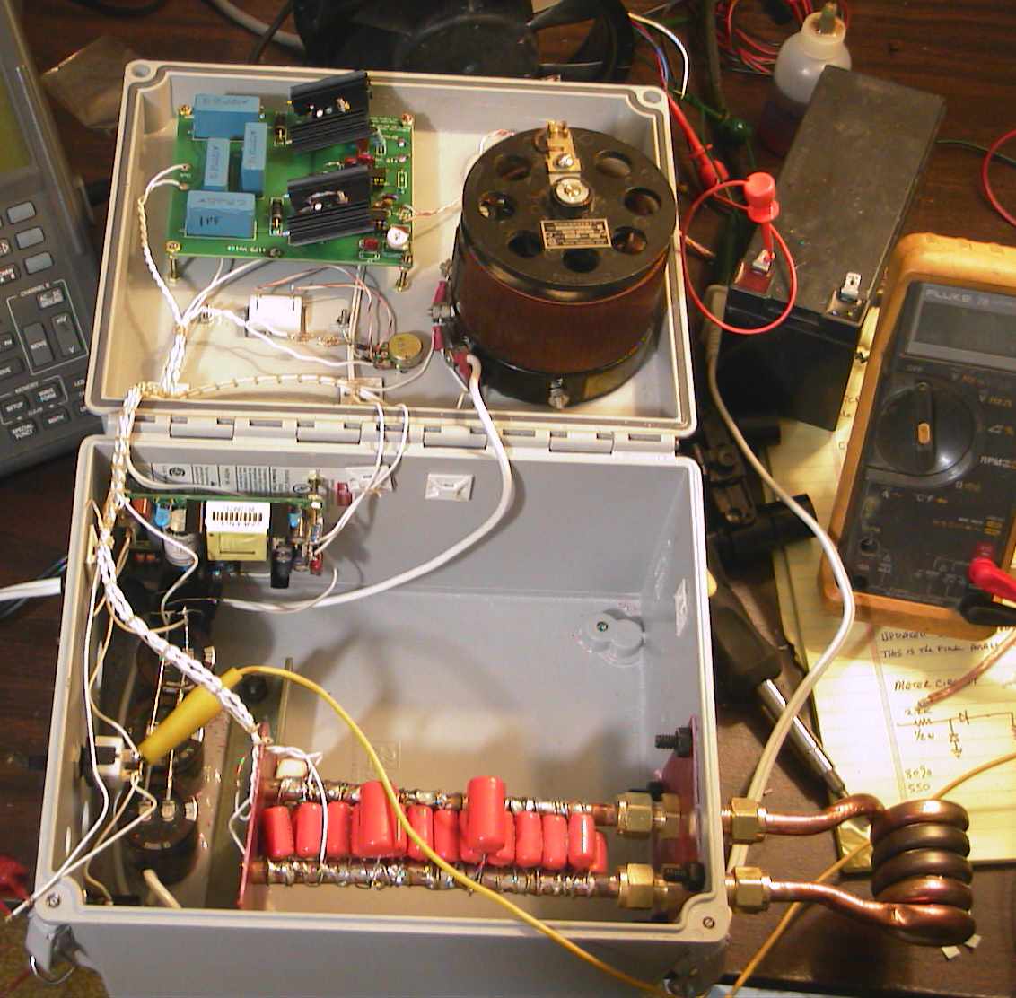
 Several views of the inside of the box. Important
note: The heat sinks shown in the photo are NOT large
enough for continuous use. With fan cooling they're good for about a
minute. That's more than enough for processing getters and lamp
electrodes. If you plan on using this heater for longer durations, you
MUST fit larger heat sinks.
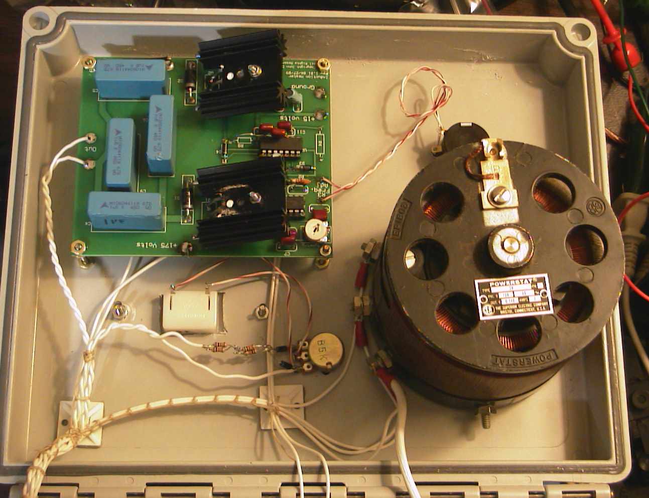
Several views of the inside of the box. Important
note: The heat sinks shown in the photo are NOT large
enough for continuous use. With fan cooling they're good for about a
minute. That's more than enough for processing getters and lamp
electrodes. If you plan on using this heater for longer durations, you
MUST fit larger heat sinks.
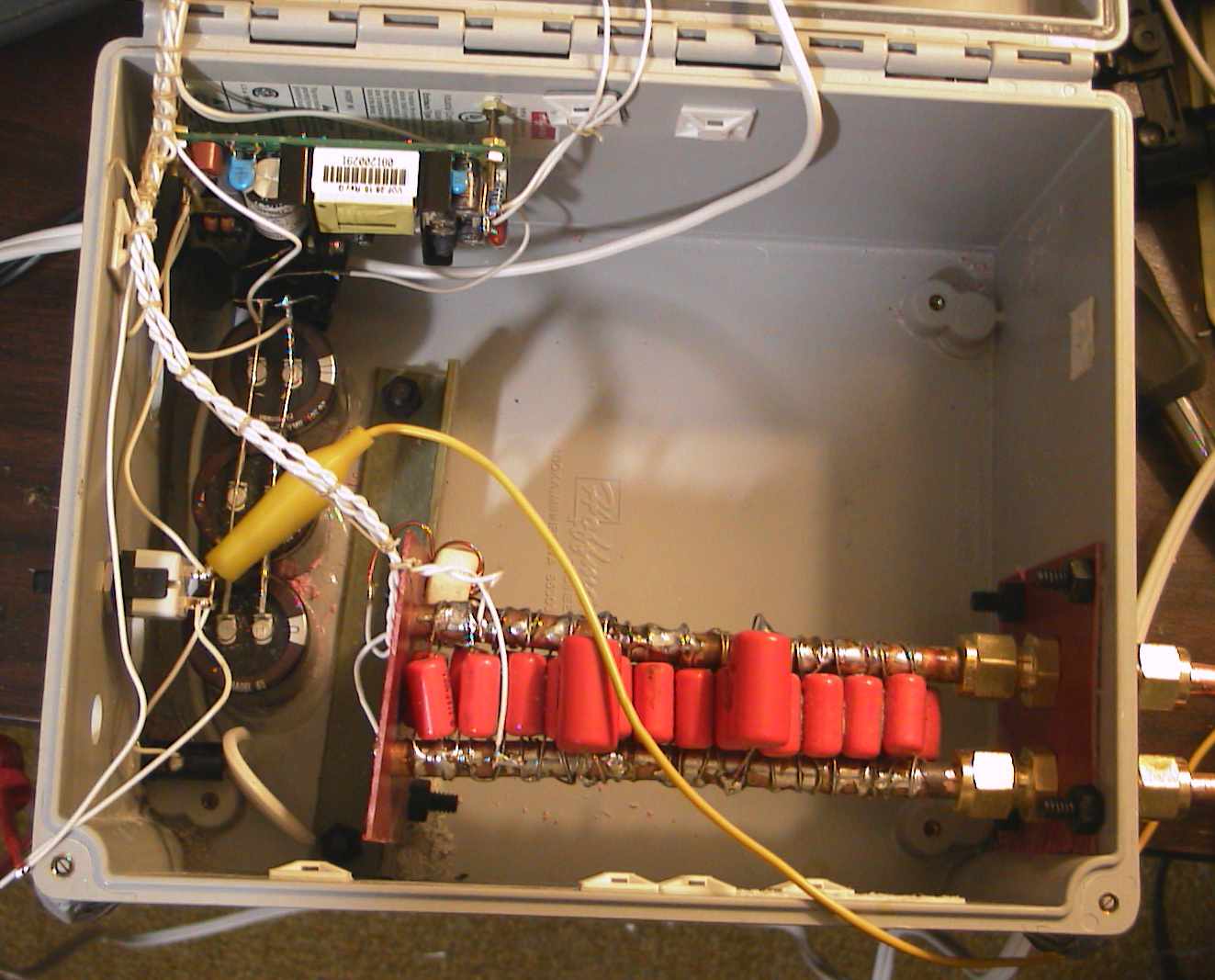
Two views of the tank circuit. Because several hundred amps flows in the tank, the conductors must be heavy. The current must be spread across many capacitors. The capacitors are polypropylene "Orange Drop" caps. There are 24 0.022uF, 400 volt caps and 2 0.1uF 400 volt caps for a total capacity of 0.7305uF. This resonates with the 5 turn coil at about 300khz.
These photos show some details of the enclosure. While you probably won't use the same enclosure that we did, the photos illustrate some important features.
The first point is that the box and everything surrounding the tank is non-metallic. We would not want to be heating the enclosure! The pink electrical fiberglass board was used because I expected the bulkhead couplings to get hot from the current. I was not disappointed. The fiberglass-reinforced plastic box might have been able to handle the heat but I chose not to take a chance. The bulkhead fittings were used so that the coil could be easily and quickly changed for a different size.
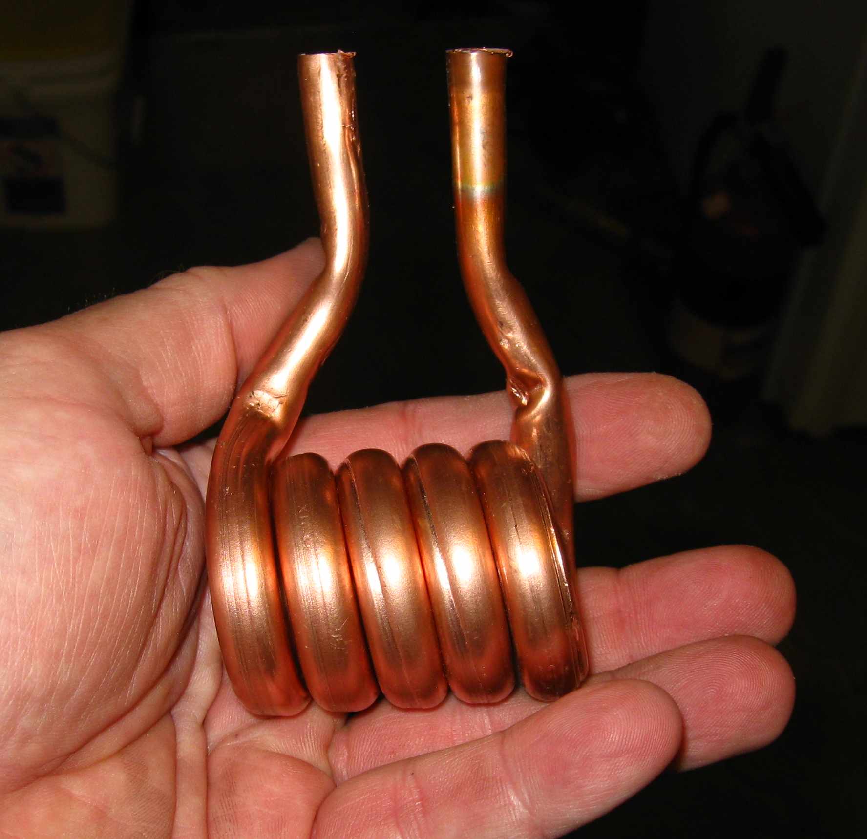
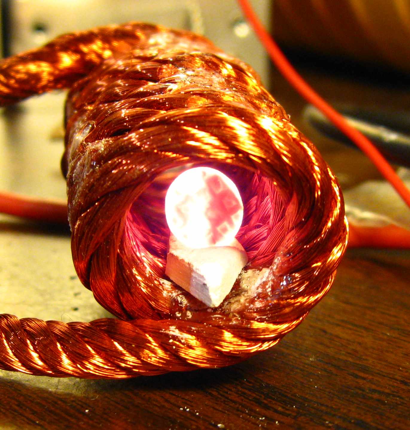
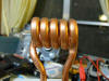
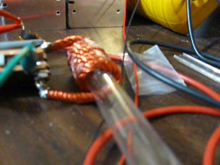
The work coil. This coil was designed to heat cold cathode lamp components and so is fairly small. It has a 1" ID. It is constructed from 3/8" soft copper tubing. The coil can be any size as long as the inductance is about 0.385uH to resonate at 300khz. Note that the resonant frequency isn't critical but the tuning range of the oscillator chip chosen for this project is limited to from about 260kHz to 320kHz.
The inductance is too low to measure with most commonly available equipment but it can be calculated. This program is based on work done at the National Bureau of Standards and is quite accurate. Note: The program is distributed in source form. It makes just fine under Linux, the OS that I run. If someone would make this program under DOS or windows, I'd be most appreciative if you sent it to me so that I can post the executable here.
For details on how to wind this coil, click on the side bar above.

The Schematic - what everyone is waiting for :-) Here is the schematic in the native Express PCB format. For an explanation of how the circuit works, click the side bar above.
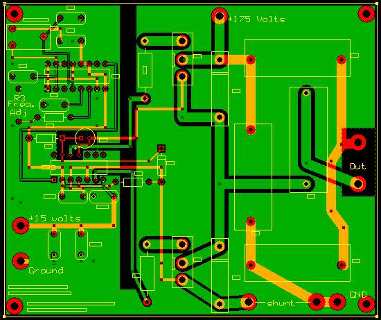
PCB Board layout. Here is the layout in the native Express PCB Format. Important notice: We are providing this layout file for your own personal use, in case you want to have your own board made by ExpressPCB. (Not sure why you would, considering their NRE fees for only a board or two.) You may NOT make boards for sale or give-away to others.
In the event we decide not to sell the "hard to find" parts kits and you want to get up a group buy on boards, write Garett or me for permission. As long as it is a genuine group buy and not a business venture, we'll grant permission.
Important note #2: I have a revised board in progress that will put the power FETs on the edge of the board so that heat sinking them will be easier. This board works but unless you're in a real hurry, I suggest waiting for the next revision.
External Schematic - This is the schematic of the connections external to the PCB.
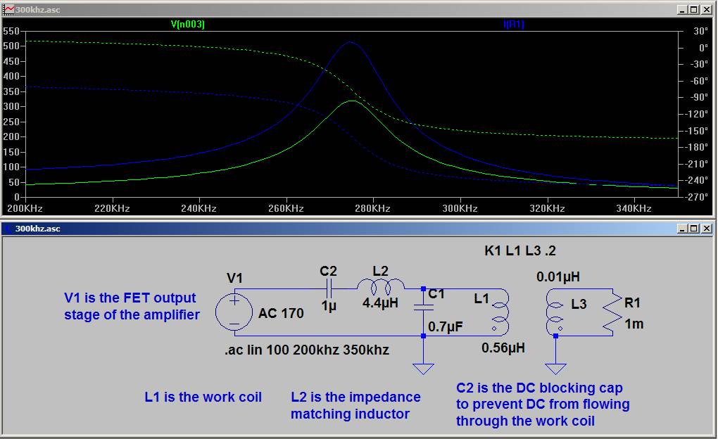
The SPICE Model - Like Richie Burnett, I developed a SPICE model to simulate the behavior of the driver, matching coil and tank circuit. My model is a bit more detailed than his in that I developed the mutual inductance model of the coil and work. I have tweaked this model so that it matches my measurements to a close degree. A couple of notes.
The coupling factor will vary widely, depending on the dimensions of your coil and the work object. This factor in the model, along with the secondary (work) inductance and resistance will also vary widely depending on geometry. This is something that requires a bit of iteration - you have to play with it a bit.
I set the source impedance to 2 ohms because that made the model fit measurements. Given that the Rdson resistance of the FETs is just a few milliohms, one would think that the source impedance would be significantly less. That 2 ohms makes the model behave probably reflects the distributed inductance in the wiring and filter caps and the less than 100% stiff power supply.
Click here to download the model. The Free LTSpice program can be downloaded here.
Here is a vid showing the heater firing a 10mm getter. This gives you an idea of how fast the unit is.
Another vid showing a 10mm getter being fired, this time by a Litz wire work coil. Litz wire is made of of individually insulated strands - 1700 in this case - of copper wire. It is designed to minimize the losses due to skin effect. While this coil is more efficient than the copper tube one, it cannot be water cooled and therefore is not practical for anything other than very short duration heats.