Home

 
Email John
Last update 02/17/2009

Ribbon Burner


I designed my ribbon burner from scratch after observing the various commercially available units.  I had several criteria.  First and foremost, self-contained except for the gas supply.  I did not want to have to supply high volumes of compressed air to the burner like most commercial burners require. 

Next, foot pedal controlled.  My shop is air conditioned and having the ribbon run all the time would have swamped the AC, not to mention costing a fortune.  This also implies

Auto ignition.  Hit the pedal and the fire starts.

Easy to adjust.  Some commercially available ribbons are a real pain to adjust.

Very cheap to build.

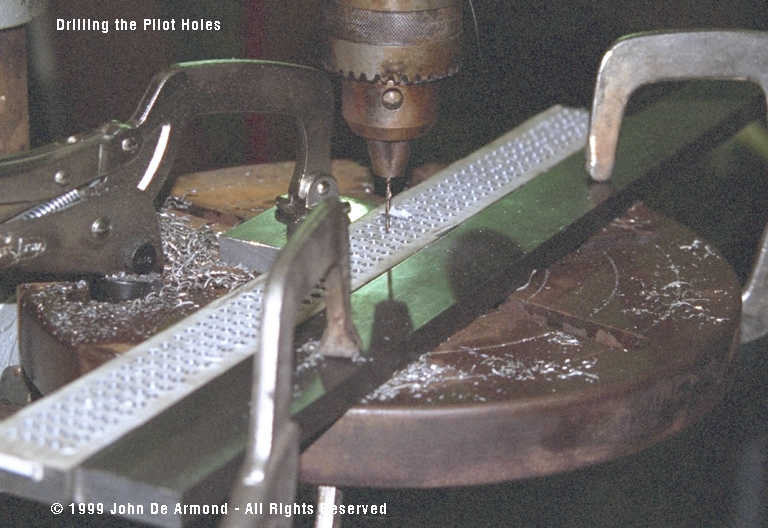
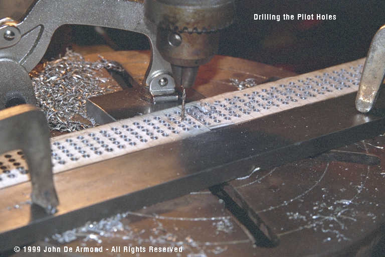
As you'll see below, I even fabricated the burner screen from scratch which took me almost a whole weekend at the drill press to do.  Doing it over again, I'd have spent the money for a replacement screen for a commercially made burner.

Ribbons burned since 05/27/07

Be sure to REFRESH each page on this site as I'm adding content on a daily basis.


This is the completed unit. Visible here is the pilot light sustainer module that I use for auto-ignition and the blower that supplies combustion air.  Not visible is the base, an old car rim.  The rim is heavy enough to make the unit very stable.
Air and gas mixer.  A simple black iron Tee welded to a black iron floor flange.  I chose welding to make a more compact assembly than possible using a close nipple.  The mounting holes are welded up on the flange because they were in the wrong place.  The fan opening is large enough that they fell over the opening.

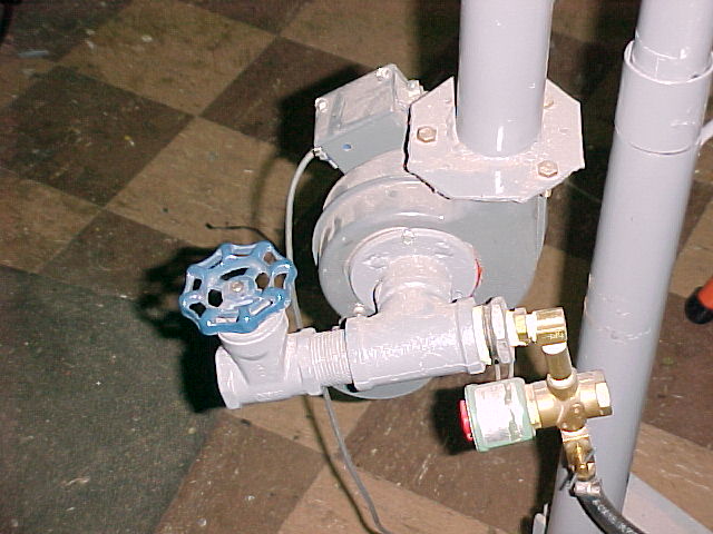
I chose to mix the gas and air before the blower for a reason.  The spinning blower wheel makes an excellent gas mixer.  This ensures a very uniform mixture to the burner screen.

Note that I have 2 psi gas service in my shop.  If I had low pressure service I'd have needed a larger solenoid valve, needle valve and hose.

 
Details of the screen showing the igniter and the screen holes.  The igniter electrode comes with the pilot sustainer.  It must be bent and trimmed to dimension.  The high temperature metal used for the electrode is brittle at room temperature and will break if bent.  Heat the metal red hot with a torch before bending.

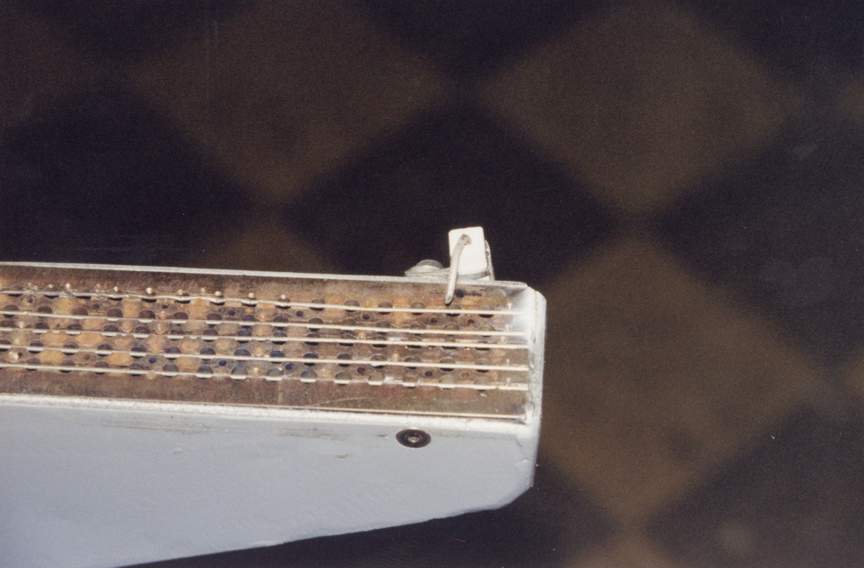
The screen shows several features.  The velocity of the mixture though the screen holes must exceed the combustion speed or else the flame will back down the hole and cause a flashback.

After laying out the screen with the correct size holes I realized that I'd have hundreds of holes to drill.  I came up with a clever method of cutting those in half.  I drilled larger holes, then cut grooves through the centerline, then placed and staked stainless steel wire.  This wire effectively makes two holes out of one, increases the velocity and prevents flashbacks.

The small holes are called pilot holes and serve to anchor the main flame at higher flame levels.

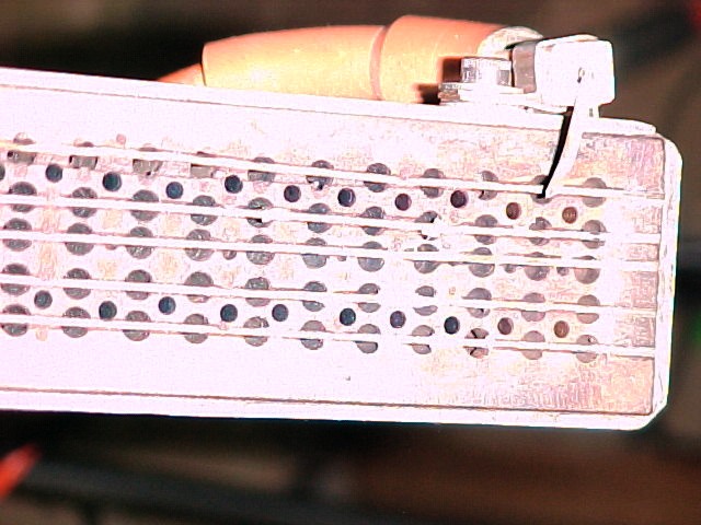
As the gas velocity exceeds the combustion velocity, the flame will lift off the screen and tend to blow out.  The velocity through the small holes is much lower so the small flames remain attached to the plate and serve as a sort of continuous ignition source for the main holes.

The pilot holes permit a much larger flame than would be possible without them.  They were only needed on the outside, as the flame itself serves to pilot the center holes.

Another shot of the screen and igniter from a different angle.  
Welding the box.  The box is constructed from 11 ga sheet metal that I happen to have laying around.  It's thick enough to easily stick weld plus it's strong enough to resist the forces of a backfire.

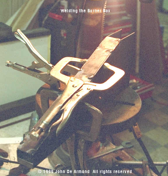
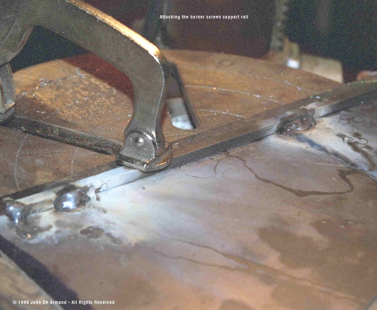
I have no special sheet metal tools so this metal was cut using an abrasive blade in my circle saw.  It was dressed with a hand grinder and then jigged up and welded.

Once the box was fabricated it was loosely filled with very coarse steel wool.  This serves to slow and evenly distribute the gas flow.

 Metal lathe turnings would work too. 

Commercial units use a variety of baffles but the steel wool trick is easier to do.

Welding on the slide guides.  The guide material is 1/4" key stock.  
Drilling the screen.  The screen is half inch cold rolled steel, 1 inch wide.  I used other pieces of stock to make up the sliding jig that made drilling relatively fast.  I plotted the hole pattern on card stock and glued it to the metal stock as the drill pattern.  Drilling through the paper eliminated the need to center-punch each hole, as the paper served to anchor the bit.

I used a tungsten nitride coated (gold) drill bit and trichloroethane "trike" as the cutting fluid.  The nitride coating is amazing.  I bought a whole package (10) of bits thinking I'd need that many.  One bit did the job and was still sharp at the end.

Trike is an amazing cutting fluid.  It used to be the ingredient in Tap Magic steel tapping fluid before the eco-hysteria over chlorinated solvents.  It is still available as CRC brand contact cleaner and some aerosol brake cleaners.

There must be some sort of chemical reaction at the cutter-stock interface, for there is a constant ripping sound of little explosions when drilling.  It literally feels like passing a knife through butter.  I'd estimate the drilling speed at three times that of a dry bit.  There is simply no comparison between Trike and other cutting fluids, even the sulfurized ones.
Drilling the pilot holes
Corel 5 file of the screen template Full size EPS file