RV Battery Isolation Relays

Many motorhomes contain two 12 volt electrical systems and batteries. One, called the chassis or cranking battery, is used to crank the engine and operate chassis/drivetrain-related components such as headlights and the dashboard. The second, called the house battery, operates the RV part of the motorhome.
Since we don't want to run down the chassis battery while using the RV lights, the two systems must be isolated from one another. Yet it is desirable to let the engine alternator charge both systems when the engine is running. Ergo, we need some means to connect the two to the alternator when the engine is running and separate them when it isn't.
One method is to use a diode isolator that consists of two heavy duty diodes mounted to a heat sink. The anodes are connected together and connected to the alternator output terminal. One cathode goes to the chassis battery and the other goes to the house battery.
While the diode isolator works when the OEM electrical system is designed for it, for a variety of reasons it isn't the best solution. A simple heavy duty relay or "solenoid" is the much better and simpler solution.
The System
The interconnect relay system is quite simple, consisting of nothing more than a single pole single throw contactor, a source of 12 volts that is only on when the engine is running and optionally, a control switch. Here is a wiring diagram of the circuit.
 On
the upper left is the chassis system and on the right the house system.
Physically, these connections are normally made to the respective battery's
(+) terminals. In the center is the single pole, single throw
relay/contactor. Below that is the control switch and below that is the
incoming switched 12 volts.
On
the upper left is the chassis system and on the right the house system.
Physically, these connections are normally made to the respective battery's
(+) terminals. In the center is the single pole, single throw
relay/contactor. Below that is the control switch and below that is the
incoming switched 12 volts.
Ideally this switched 12 volts will come from something that actually indicates that the engine is running. The most common is an oil pressure switch. Some alternators have a "running" output. If neither of these sources is convenient to use or install then simply use the switched 12 volts that is energized only when the ignition key is in the "run" position. This is the usual OEM way of doing it. The objective is to energize the interconnect relay only when the engine is running and the alternator is alternating :-)
The solenoid relay has another benefit. If sufficiently heavy cable is run between the batteries and the relay, the relay can be energized manually to provide a "self jump-start" in the instance when the cranking battery runs down. Most motorhomes that use isolation relays also have a manual-off-auto switch. In the manual (also known as "boost") position the solenoid is always energized. In the Off position the solenoid is never energized. In the Auto position the solenoid is energized when the engine is running. The Manual position hooks the house battery in parallel with the cranking battery so the house battery can boost off a weak cranking battery. Or if you've flattened your house batteries, simply flip the switch to "boost" and crank the generator with the cranking battery. Or crank the main engine, of course.
Few OEMs provide this manual-off-auto switch but I consider it valuable enough to install one yourself. The OEM switch is normally spring-return from the "boost" position. This is to prevent absent-minded knuckleheads from leaving it in the boost position and running down both sets of batteries. Since you're reading this, you're obviously above average and would never do that! Even I include a pilot light to remind me that the switch is in boost.
Having the boost position non-spring-return is very handy. When your motorhome is parked for a long period and shore power is connected, simply flip the switch to "boost" and let the converter/battery charger keep the cranking battery charged too.
There is one additional requirement for the boost feature to work. The battery wiring (shown as heavy lines in the above diagram) must be of heavy gauge, as heavy as the cable going to the starter. I normally use about #2 to #0 welding cable for gas engines and #0000 for diesels. The larger wire is necessary for diesels, of course, because of the much higher cranking current these engines require.
Many OEMs skimp in this area, using only 10 or 8 gauge wiring. Large enough to charge the batteries but far too small to boost the engines. It's worth the benefits to rip out the OEM wire and install cabling in its place.
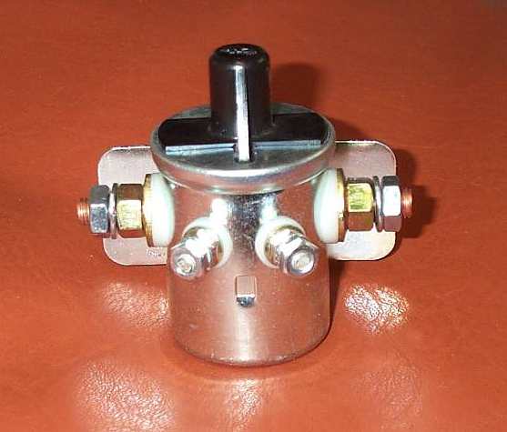
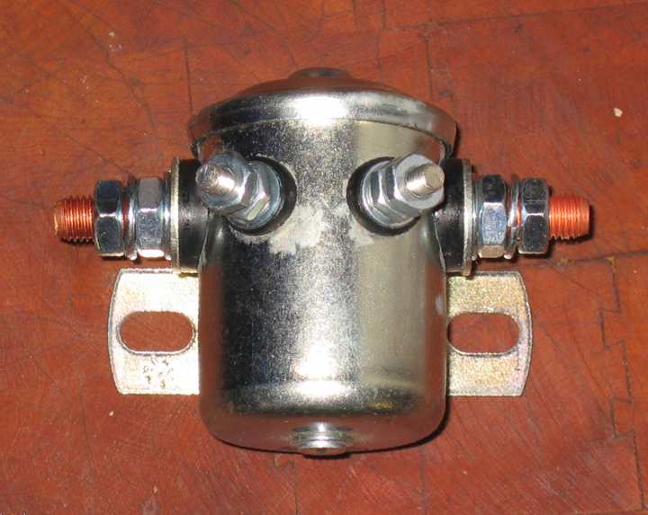
The Relay
In its simplest form, the relay is a simple single pole single throw (SPST) relay with a 12 volt continuous duty coil. In fact it looks just like an automotive starter relay. It isn't. The main difference is that a starter relay draws much more current so that it will energize even with a very weak battery. This high current draw will burn out the relay if applied for long.
If you have an unknown solenoid relay on your hands, the easy way to tell a disconnect relay from a starter relay is to measure the coil resistance.
Starter relay 3-5 ohms
Isolation Relay 12-20 ohms
There are several varieties of isolation relays. One type has only one coil terminal, the other end being grounded to the case. Another has two coil terminals. Starter relays look similar but a two terminal starter relay uses one terminal for the coil (to ground) and the other terminal switches out the ballast resistor to boost the ignition voltage when the relay is energized and the starter is running. Look-alikes but totally different functions.
In an emergency a starter relay can be used but only if some
external current limiting resistance is supplied. A lamp or perhaps an
ignition ballast resistor might do the job. Note that I have not
actually tested this so caveat emptor.
An automotive Starter Relay will burn out when used as an isolation relay.

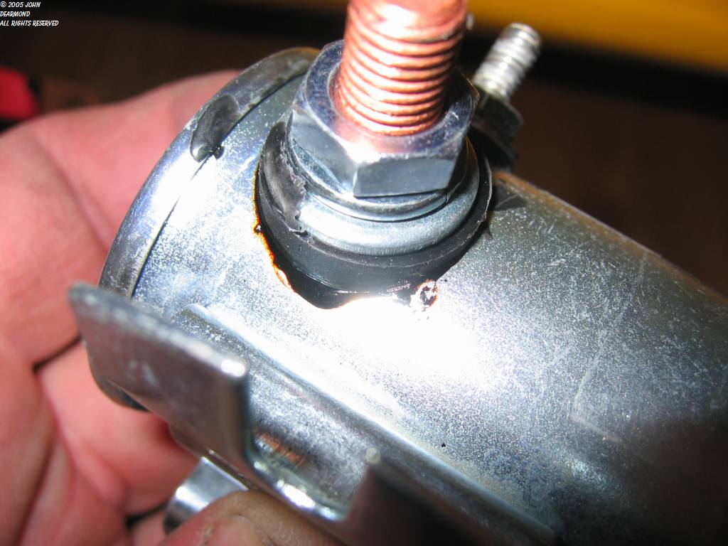
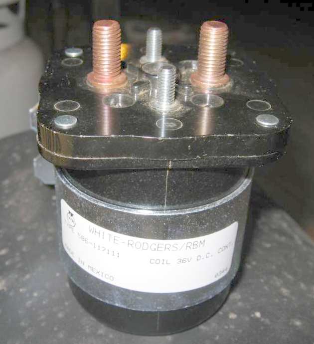
Note that this type of latching relay is normally NOT used as an isolation relay. I picture it here to show how similar it looks to the garden variety isolation relay.