| Home |
| Buck Converter |
| Flux Concentrator |
| Email John |
| Created 08/13/09 Last update 02/05/2011 |
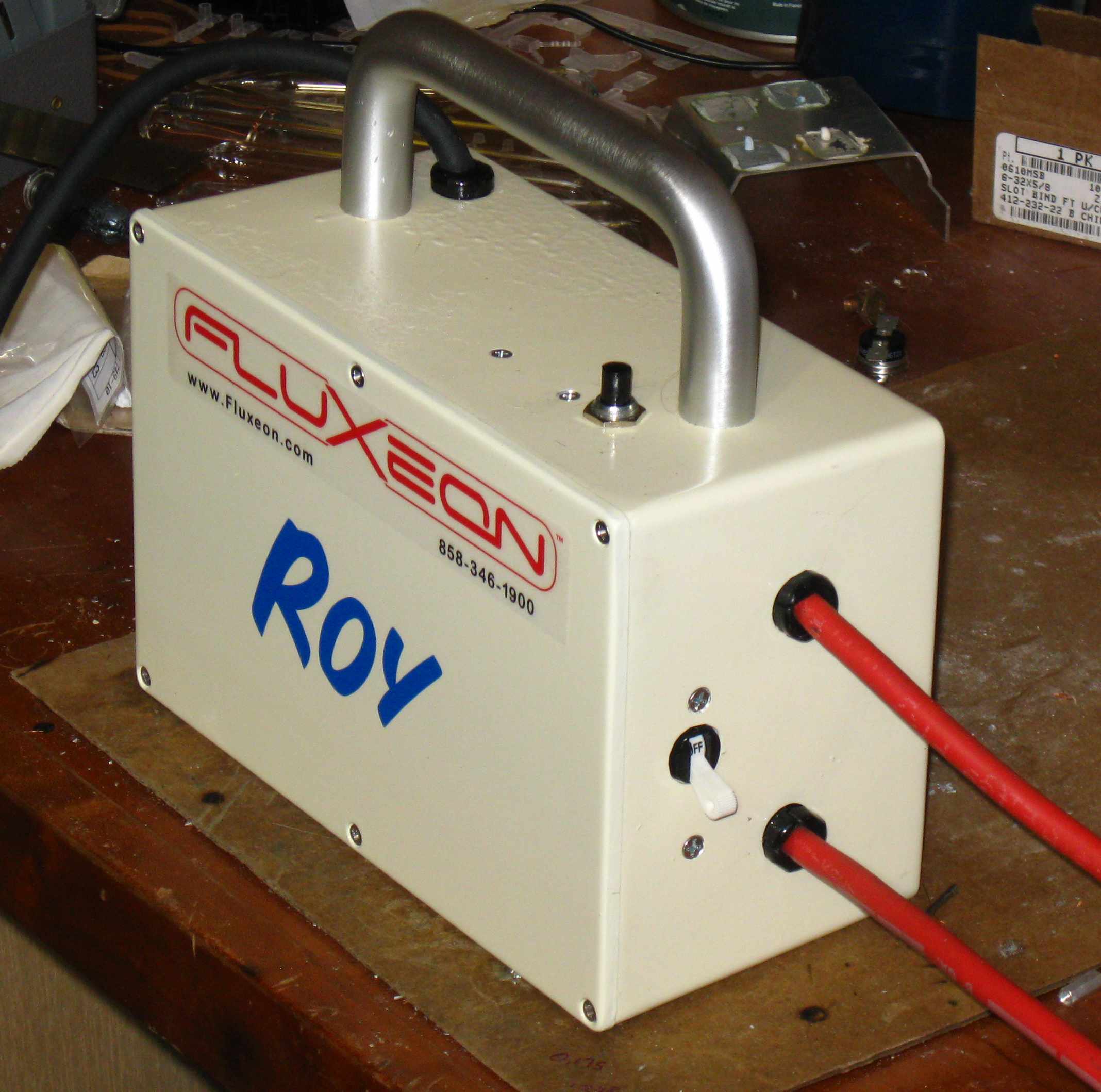
A 1.8kW Royer Induction Heater Rev 2.21

UPDATE 02/205/2011-1 - Just a reminder that neither Fluxeon nor I can provide one-on-one support for kits. If you have problems, what I recommend is joining the mailing list and post your problem there. I monitor the list so I will lend assistance when I have time.
UPDATE 02/05/2011-2 - Added a warning about small work coils and about using a current transformer to protect the transistors.
UPDATE 11/30/10 - Added a page on the use of Flux Concentrators.
UPDATE 10/30/2010 - This is a MAJOR update that partially obsoletes some of the main article. Please read this update before attempting to build this heater. Click HERE to go directly to it.
UPDATE 06/05/2010 - A note about high power and high duty cycle.
UPDATE 06/02/2010 - Buck Converter for power control added
UPDATE 05/26/2010 - a Spice model is added.
UPDATE 05/25/2010 - A mailing list for the discussion of induction heating and heaters has been established. You may subscribe by clicking here.
A few months ago I introduced an incredibly simple Royer oscillator-based induction heater, named "Roy". Roy worked well but had some limitations because the gate drive was derived from the actual output signal and therefore was poorly controlled. Roy Rev 1 was good for about 1000 watts but not much more before damaged IGBTs resulted.
Roy Rev 1 was also particular about how power was applied. It would burn out the IGBTs if high voltage was present even for an instant when the 15 volt supply was not. While that's a manageable situation, it would be better for that problem not to exist. For reference purposes, the old page can be viewed here.
To solve these problems I redesigned Roy, now known as Roy 2 or "Roy SC". This new design is presented here. the major difference is that the gate drive is now positively controlled by a digital circuit and gate driver. The nice, clean and well timed gate drive allows the heater to run up to 1800 watts. (I've driven the heater higher but 1800 is about all one can get out of a 20 amp branch circuit.) Without further ado, let's look at the new design.
The Royer power oscillator-based induction heater is an incredibly simple yet very powerful design. Though the Royer architecture is ubiquitous (your laptop's backlight driver probably uses one), there seems to be very little information on the net about how the architecture works. I'm going to address that problem and present a very simple but very powerful induction heater based on the architecture.
The Basics
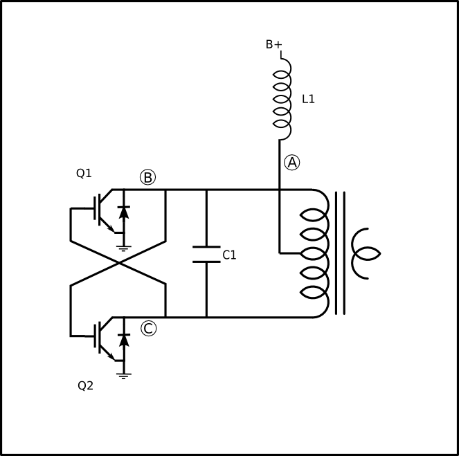 The
diagram shows the basic Royer oscillator. It consists of a transformer
with a center-tapped primary, a choke labeled L1, two semiconductors
(here shown as IGBTs though they could just as well be FETs or bipolar
transistors) labeled Q1 and Q2, a resonating capacitor labeled
C1 and cross-coupled feedback illustrated by the crossed lines. In
a real world oscillator there will be other components such as steering
diodes, bias resistors and so on but this simplified drawing shows all that
is necessary for the basic Royer.
The
diagram shows the basic Royer oscillator. It consists of a transformer
with a center-tapped primary, a choke labeled L1, two semiconductors
(here shown as IGBTs though they could just as well be FETs or bipolar
transistors) labeled Q1 and Q2, a resonating capacitor labeled
C1 and cross-coupled feedback illustrated by the crossed lines. In
a real world oscillator there will be other components such as steering
diodes, bias resistors and so on but this simplified drawing shows all that
is necessary for the basic Royer.
Operation is as follows. When power is applied at B+, DC current flows through the two sides of the transformer primary and on to the transistors' collectors. At the same time the voltage appears on both gates and starts to turn the transistors on. One transistor is invariably a little faster than the other and will turn on more. The added current flowing in that side of the transformer does two things. One, it robs drive from the other transistor. Two, the auto-transformer action impresses a positive voltage on the conducting transistor, turning it hard on.
The current would continue to increase until the transformer saturated were it not for C1, the resonating capacitor. The capacitor causes the voltage across the primary to first rise and then fall in a standard sine wave pattern. Let's say that Q1 turned on first. The voltage at point B will be clamped to near ground while the voltage at point C rises to a peak and then falls as the tank formed by the capacitor and transformer primary oscillator through one half cycle.
As the voltage at point C passes through zero, the drive to transistor Q1 gate is removed, turning it off. That allows the voltage at point B to start rising and in turn, turn Q2 on. Q2 clamps the voltage at point C to near zero, ensuring that transistor Q1 remains off. Then the same sequence as described for Q1 above occurs and the oscillator completes one cycle.
The oscillator runs at the frequency determined by the inductance of the transformer primary, the capacitor value and to a lesser extent, the load applied to the secondary. Generally, a good place to start to determine the operating frequency is the familiar formula for resonance,
F = 1/ 2*pi*sqrt(LC).
The Royer heater that I present here runs at about 100 kHz, depending on the load.
Waveforms
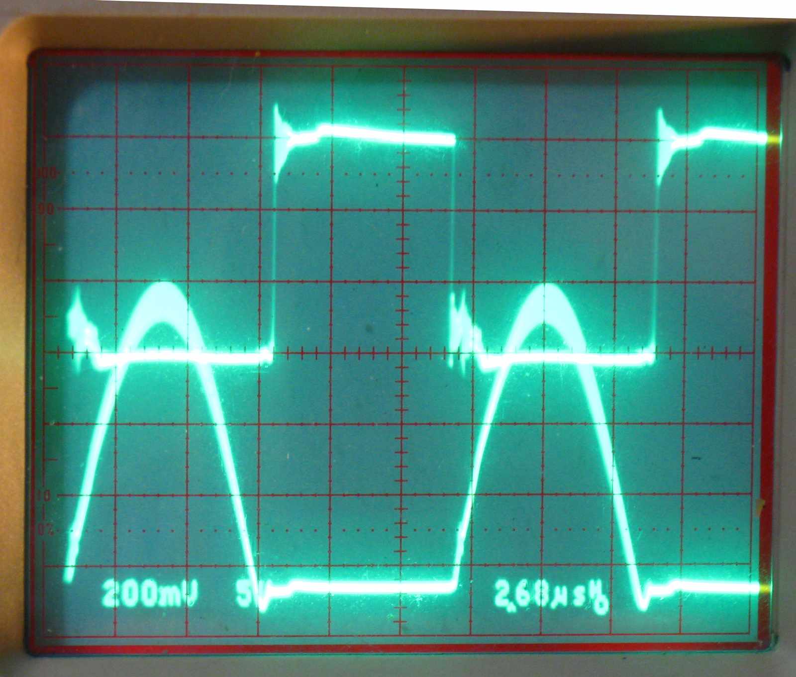 This
scope shot shows two important traces. The top trace is the gate drive
of Q1 while the bottom trace is the voltage at point B.
As you can see, when the gate drive of Q1 is on, the voltage at point
B is clamped to near ground. When the half-cycle is complete
and the gate drive turns on, the voltage at point B soars. This
is the signal that drive the gate of Q2.
This
scope shot shows two important traces. The top trace is the gate drive
of Q1 while the bottom trace is the voltage at point B.
As you can see, when the gate drive of Q1 is on, the voltage at point
B is clamped to near ground. When the half-cycle is complete
and the gate drive turns on, the voltage at point B soars. This
is the signal that drive the gate of Q2.
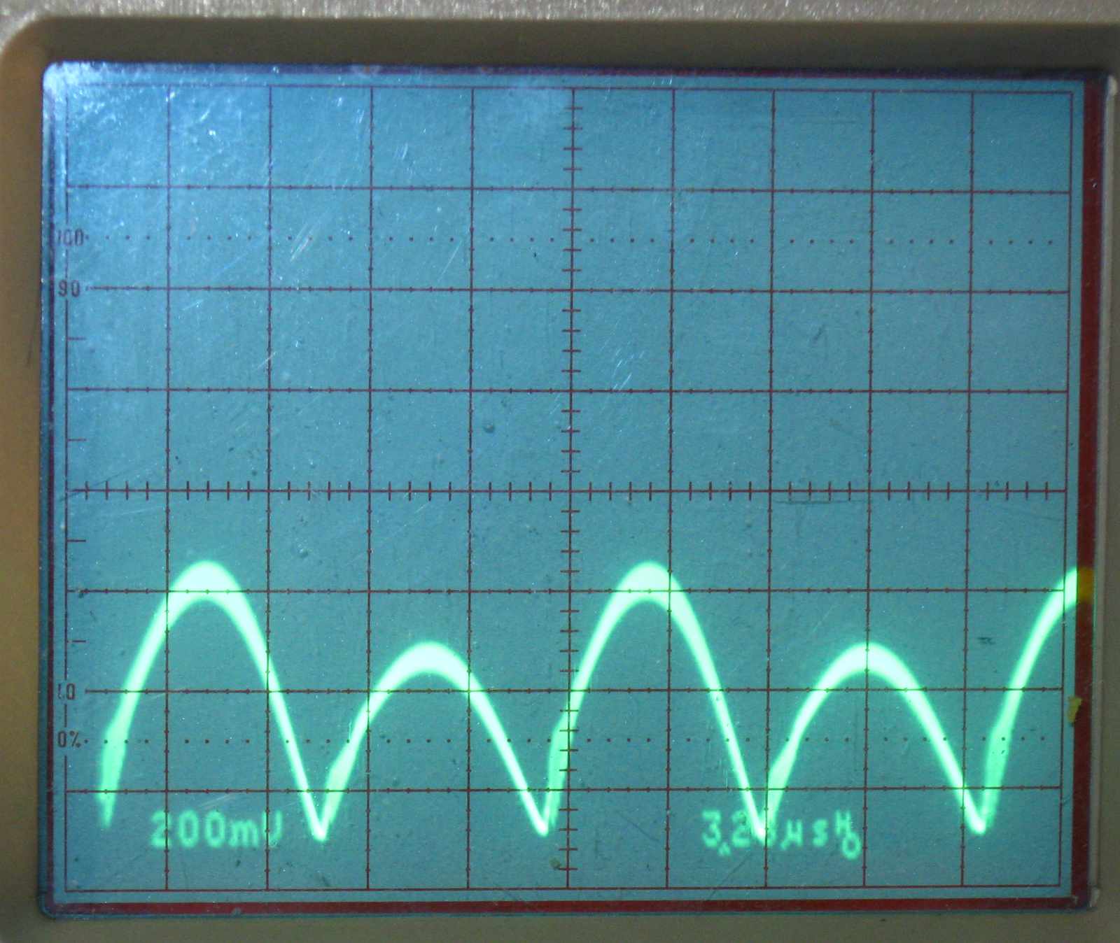 This
photo shows the waveform at point A. Here you can see both
half-cycles happening. They should be of equal amplitude but in every
Royer oscillator that I've ever built, one side is slightly larger than the
other. I have no explanation.
This
photo shows the waveform at point A. Here you can see both
half-cycles happening. They should be of equal amplitude but in every
Royer oscillator that I've ever built, one side is slightly larger than the
other. I have no explanation.
This illustrates another important point. This is a Current Fed Oscillator. This is a term that is used frequently in the induction heating literature. What it means is that because of the inductor, the current flowing through the transformer and FETs is practically constant (a square wave) while the voltage varies as a sinusoid.
The other induction heater that I present on this site, the half bridge secondary resonant one, is a Voltage Fed Oscillator. In that instance, the current through the coil varies as a sinusoid while the voltage is constant for each half cycle.
The Real Thing
The heart of the new system is the flip-flop formed around U1. The operating principle may be a bit difficult to understand at first glance. When power is applied the gates race to see which one will go true (logical 0 output) first. The one that wins sends a logical 1 to the attached MC33151 gate driver. This is an inverting driver so the 1 causes that IGBT to remain off. The "losing" gate of the flip-flop sends a 0 to the gate driver which turns on that IGBT. The IGBT pulls that side of the coil down, causing current to start flowing. The voltage remains near ground which feeds back to the losing gate, keeping the winning gate firmly false and that IGBT off.
 Because
of the capacitor across the coil, the voltage rises to a peak and then
declines. This voltage shows up on the "off" IGBT. When the
voltage reaches almost zero again, this gate goes false, outputs a 1 and
changes the state of the other gate. This turns off the formerly on
IGBT and turns on the formerly off one.
Because
of the capacitor across the coil, the voltage rises to a peak and then
declines. This voltage shows up on the "off" IGBT. When the
voltage reaches almost zero again, this gate goes false, outputs a 1 and
changes the state of the other gate. This turns off the formerly on
IGBT and turns on the formerly off one.
A very important concept and the reason this architecture works so well is that the switching is done at the Zero Voltage Point (also the zero current point). The IGBT has to switch essentially zero current at essentially zero voltage. Therefore there are no switching losses. Even more importantly, the IGBT remains inside its Safe Operating Area (SOA). Violate the SOA and all the blue smoke leaks out.
The above process continues as long as power is supplied to the device. Like Roy 1, Roy SC's power output is determined by the number of turns on the secondary of the transformer and the configuration of the work coil. I strongly recommend using a Kill-A-Watt when setting up Roy SC.
The schematic in ExpressPCB format is here and in PDF format here..
Weakness
This heater also has a weakness which can burn out IGBTs but it is much easier to manage. It revolves around the necessity to always maintain ZVS. Deviate from ZVS and the transistors can quickly exceed their SOA and burn out.
The time when this will always happen is if high voltage is applied before the 15 volt logic supply. When the 15 volt supply is applied, whichever IGBT "loses" suddenly has to switch 160 volts at high amperage to start the oscillation. This exceeds the SOA and the transistor smokes. It invariably smokes the other one too.
This problem is easily avoided by ensuring that the 15 volt supply is always present before applying high voltage. When the 15 volt supply appears, the unit starts oscillating at 15 volts. Therefore the ZVS conditions are established when the high voltage is subsequently applied. My commercial version of this unit contains protective circuitry that inhibits IGBT firing if high voltage is present. It also has a processor that controls the high voltage to make sure that it can't be present at the wrong time. This open source version doesn't have those features but the external wiring is designed to accomplish about the same thing. See the explanation below.
 Here is the board layout. The actual board in ExpressPCB format is
here. As with the other induction heater, you may use this board
for your own personal use. If you want to use this design or board for
commercial purposes including group buys, then you must contact us for
permission. Email addresses at the left. If you just want a
board, then contact Garett and see what we have in stock.
Here is the board layout. The actual board in ExpressPCB format is
here. As with the other induction heater, you may use this board
for your own personal use. If you want to use this design or board for
commercial purposes including group buys, then you must contact us for
permission. Email addresses at the left. If you just want a
board, then contact Garett and see what we have in stock.

Here is the external wiring schematic. Simple, huh? That screen capture is impossible to read so here is the actual schematic in ExpressPCB format and here in PDF format. This architecture, specifically K2 is designed to avoid the problem I described above. Specifically, the relay will not allow high voltage to flow to the board until the 15 volt supply has risen to the realy's pick-up voltage, about 9 volts which is plenty. More importantly, when power is lost for whatever reason, the relay drops out at about 6 volts. When it drops out it immediately opens the high voltage circuit AND it discharges the filter cap through the 20 ohm resistor. The discharge happens in a fraction of a second, faster than the decaying 15 volts can decay to zero.
Bill of Material
If you really want to go through the agony of acquiring all the parts to make one of these boards, here is the Bill of Material.While you're contemplating buying these parts on the open market, be aware that Fluxeon offers a complete parts kit, including parts such as the inductor and transformer that can't be purchased in small quantities on the open market.
Another use of the BOM, of course, is to check in your parts kit after you've acquired it from Fluxeon.
Use
Unlike the other heater, this heater is only semi-resonant and can use any sort of work coil including a straight piece of wire for heating long narrow parts. Also unlike the other heater, this one requires tight coupling between the work coil and the work. It would be typical to wrap with work with a work coil.
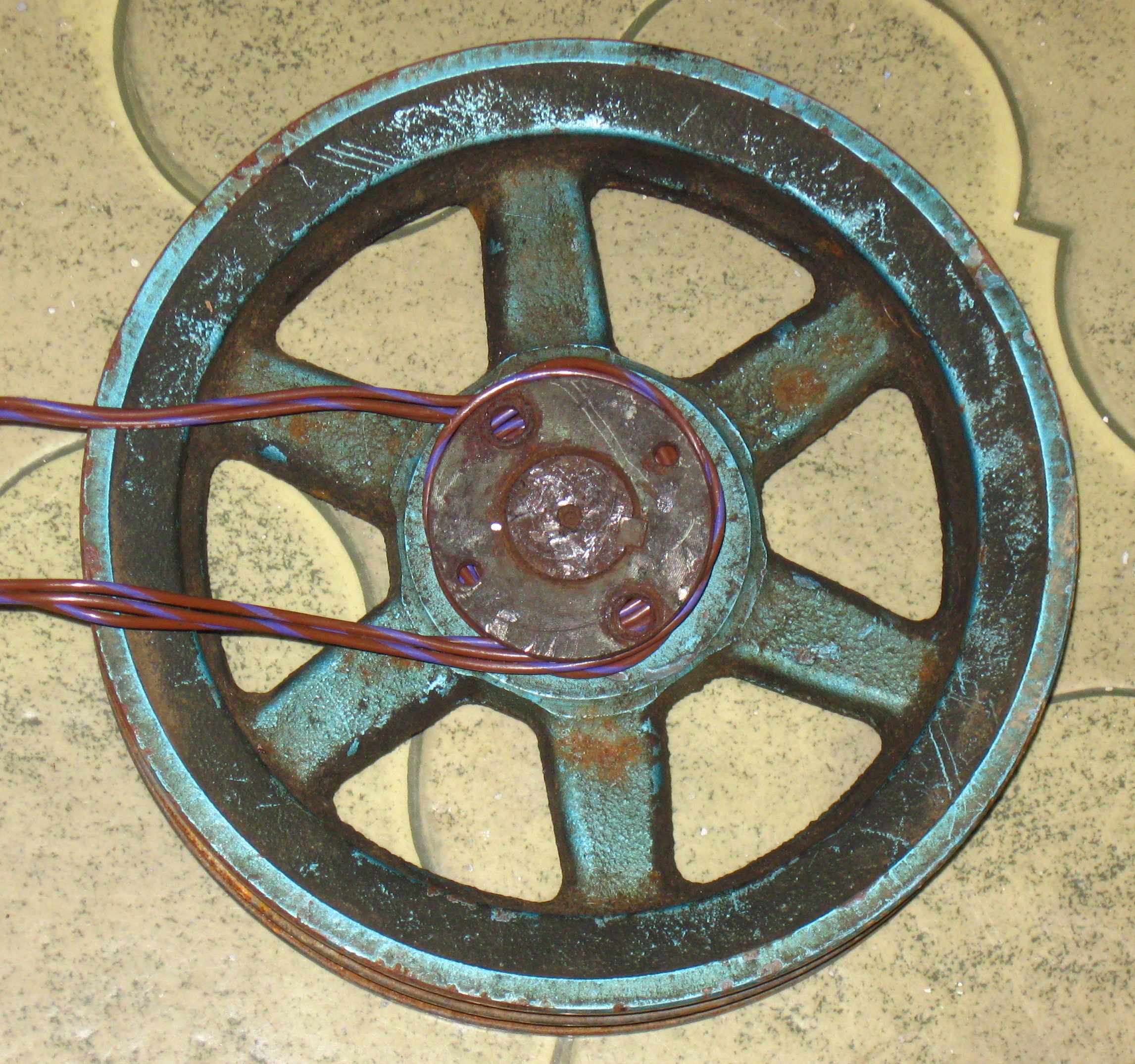 Say
you need to heat a pulley hub to get it loose from a rusted shaft.
Simply wrap several turns of wire around the hub and connect it to the
heater. Turn on the heater and in seconds the part will be heated to
several hundred degrees.
Say
you need to heat a pulley hub to get it loose from a rusted shaft.
Simply wrap several turns of wire around the hub and connect it to the
heater. Turn on the heater and in seconds the part will be heated to
several hundred degrees.
In this photo I show several strands of 16 gauge teflon-covered wire. Just what I happened to have on hand. Any sort of wire will do. 10 gauge or larger is recommended for most jobs.
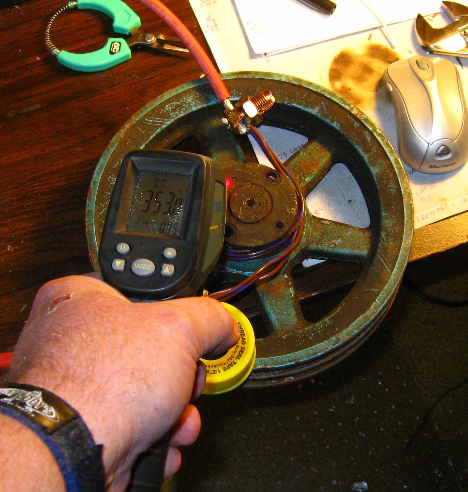 This
photo shows how well Roy works. After 1 minute of heating, the hub of
this pulley is at 353 deg F. To do this with a torch would take
several minutes and with the grease and dirt on the pulley, would leave a
burned, blackened and scorched mess. Roy did this heating with no
smoke and no soot. Not even any scorched paint.
This
photo shows how well Roy works. After 1 minute of heating, the hub of
this pulley is at 353 deg F. To do this with a torch would take
several minutes and with the grease and dirt on the pulley, would leave a
burned, blackened and scorched mess. Roy did this heating with no
smoke and no soot. Not even any scorched paint.
BTW, the real product will NOT use those split bolt connectors! I have designed a custom connector that attaches to the work coil with a simple thumb nut but those are still at the machine shop.
Protection
The amount of power delivered to the load is determined by the transformer ratio and the number of turns wrapped around the work. It is easily possible to exceed the ratings of a 20 amp branch circuit and even burn out the transistors by overloading the unit. While our commercial version has load limiting, this one does not. Therefore it is imperative that circuit protection be used. We recommend a high speed magnetic circuit breaker such as that made by Heineman or a fast acting fuse. The Heinemann trip profile is #64. The circuit breaker is available from us as well as other distributors. A household circuit breaker is NOT fast enough to protect the transistors. Be Warned: You will smoke transistors if you ignore this paragraph.
If you choose to use a fuse, you must use a 250 volt 15 amp fast action ceramic fuse. Do not use an automotive fuse!!! One of my customers did and ended up damaging the board. An automotive fuse continues to conduct for several cycles through the arc created in the glass tube. It allows through enough current to burn the traces off the board if there is a short in the IGBTs. I strongly recommend against fuses. Not only are they expensive but they're not nearly as precise as the specified circuit breaker. The specified breaker conducts 15 amps, trips at 17.5 amps and its let-through on a short is limited and short, only a cycle or two.
Commercial Unit
We will shortly have a commercial version of this unit available for sale. It includes several features not included in the simple unit presented here. Features include protection against overload, a handy package that easily fits inside machines and an extended duty cycle. Visit Fluxeon.com for information as it develops.
Kits
Fluxeon.com now offers this heater in kit form and as an assembled/tested board. Transformers, breakers and all the other parts necessary to make a functioning unit are also available. The A/T board is aimed at OEMs who want to incorporate induction heating in their product. Please check the Fluxeon web site and/or contact Garett for details.
Update 03/06/2010 -
 We
now have a very nice Magnetics
ferrite core and coil forms in stock. This core is good for >1500 watts in
Royer oscillator service. This is the core that our commercial product
is built around. Contact Garett for info on purchasing.
We
now have a very nice Magnetics
ferrite core and coil forms in stock. This core is good for >1500 watts in
Royer oscillator service. This is the core that our commercial product
is built around. Contact Garett for info on purchasing.
- I recommend using a zero crossing solid state relay to control this heater. The one that I'm using in our product is Omron model G3NE-220T-US-DC12, available from Mouser Electronics. This relay should be wired so that it gets its "coil" voltage from the same 15 volt supply that powers the board. That way high voltage can never be applied unless the +15 volts is available.
-
Note that like all solid state relays, this one has a small amount of "off" leakage. Therefore the heater will have a small amount of high voltage on it even when the relay is off. Therefore don't touch the board until the power source is removed.
Update 03/11/2010 Transformer Winding
In this section I show you how to wind a transformer using the Magnetics core. In contrast to the toroidal transformer, this type of transformer is wound on a coil form and then the core is inserted into the form and fastened in place. Let's get started. (Note: All materials mentioned in this article are available from Fluxeon.)
![]()
This photo shows the Vulcanized Fiber coil form and the start of the first layer of the primary winding. We're winding the primary out of 11 gauge equivalent Litz wire. The Litz wire is bound to the core using thick superglue and an accelerator The spot of superglue can be seen under the wire.
![]()
In this photo I have wound the first half of the primary - 14 turns. After the photo was taken, the turns were tightened up and pressed close together. Then another daub of superglue is used to secure the finish wire end.
![]()
Here we have pulled a loop of wire out that forms the center-tap - I recommend about a foot - and covered the first layer of turns with a layer of mylar/Nomex insulating paper. It is wrapped tightly around the first layer and secured in place with super glue. Then, making sure that the winding is going in the same direction, the wire is bonded to the paper.
![]()
Here the second layer is finished and the end is secured in place with superglue. The end is on the left side of this photo.
![]()
Here the inter-winding insulating paper is applied. Because this separates the high voltage primary from the low voltage secondary, it is applied two layers thick and secured with super glue.
![]()
This is a slightly larger photo showing the whole coil assembly including the leads. The loop on the left side will be twisted together to form one heavy center-tap connection.
![]() Solder
dipping the ends of the Litz wire. Most all Litz wire comes with
"solder through" insulation. That is, the insulation melts and/or
evaporates at bout 700 deg F. in this photo I'm using an inexpensive
Chinese made solder pot. Before I got the pot, I did my solder dipping
using a cast iron muffin tin heated on the kitchen stove. The solder
should be at least 700 degrees before dipping. Also, before dipping
apply some liquid soldering flux. This helps displace the insulation
and makes the solder wet the wire better.
Solder
dipping the ends of the Litz wire. Most all Litz wire comes with
"solder through" insulation. That is, the insulation melts and/or
evaporates at bout 700 deg F. in this photo I'm using an inexpensive
Chinese made solder pot. Before I got the pot, I did my solder dipping
using a cast iron muffin tin heated on the kitchen stove. The solder
should be at least 700 degrees before dipping. Also, before dipping
apply some liquid soldering flux. This helps displace the insulation
and makes the solder wet the wire better.
![]() A
close-up of the solder-dipped end. The brown crusty stuff is a
combination of flux and melted varnish insulation. It easily flakes
off.
A
close-up of the solder-dipped end. The brown crusty stuff is a
combination of flux and melted varnish insulation. It easily flakes
off.
![]() Here
is the finished primary mounted to the core. Note the shims between
the mating surfaces of the cores. This sets the air gap on the core.
The air gap reduces the permeability, increases the saturation point and
controls the inductance of the windings. The ferrite by itself is too
permeable and would saturate at a point below the useful power level that we
want. With this small 0.002" shim under each pair of poles, the
transformer is easily capable of handling 2kW.
Here
is the finished primary mounted to the core. Note the shims between
the mating surfaces of the cores. This sets the air gap on the core.
The air gap reduces the permeability, increases the saturation point and
controls the inductance of the windings. The ferrite by itself is too
permeable and would saturate at a point below the useful power level that we
want. With this small 0.002" shim under each pair of poles, the
transformer is easily capable of handling 2kW.
 This
photo shows the finished transformer with the 4 gauge welding wire
secondary. In the background is a much larger transformer core that is
good to about 10kW. Kind of a hint as to where we're headed :-).
This
photo shows the finished transformer with the 4 gauge welding wire
secondary. In the background is a much larger transformer core that is
good to about 10kW. Kind of a hint as to where we're headed :-).
For general purpose use this 2 turn secondary is just about perfect. For heating small, especially non-magnetic objects, more turns may be added.
Sharp readers will note that this transformer primary is wound with teflon covered wire. This was an early test version. The Litz wire version is far superior because the Litz wire does not significantly heat during a normal run.
 This
is a custom transformer that I made for a client. It is designed to
heat small brass parts and therefore has two parallel runs of 4 gauge
equivalent Litz wire. This transformer drives a small, low turns count
work coil. Just an example of how we can adapt this standard product
to custom needs.
This
is a custom transformer that I made for a client. It is designed to
heat small brass parts and therefore has two parallel runs of 4 gauge
equivalent Litz wire. This transformer drives a small, low turns count
work coil. Just an example of how we can adapt this standard product
to custom needs.
Performance
As one might expect, this ferrite transformer performs vastly better than the powdered iron core. The -2 formula that the other company recommended was not right for this low frequency application. The ferrite is perfect. It easily handles the power, has a large saturation margin and is physically much smaller. Plus it is a LOT cheaper.
Commercial Version
This
is a photo of the prototype commercial version of "Roy". This version
is significantly more sophisticated than the simple heater presented on this
page. It has a digital logic gate drive chain and several protective
features. It is designed for general purpose MRO (Maintenance, Repair
and Overhaul) work. In other words, most things that a gas torch can
do. Contact Garett if you're interested in this heater. He is
compiling a waiting list. No deposit necessary.
 A
friend created and sent me an
LTSpice
model of the Royer heater. I worked with the model until I got it to
produce results almost identical to those in the real world. The model
can be downloaded here. The transistor library
is compliments of Fairchild.
A
friend created and sent me an
LTSpice
model of the Royer heater. I worked with the model until I got it to
produce results almost identical to those in the real world. The model
can be downloaded here. The transistor library
is compliments of Fairchild.
You will notice that the transformer is represented by 3 coupled inductors as is usual Spice practice. The two primaries which represent each half of the actual center-tapped primary are of different values. Those are the actual values that I measured with an LCR bridge. I attribute the differences to one half being wound next to the core and the other half being wound on top of the first half.
You will also note that there is a fairly high series resistance in the high voltage power supply. This is necessary to get the model to run. Any lower than 3 ohms and the unit oscillates once and dampens out. There is apparently a flaw in the transistor model. It allows the collector voltage to rise above the 7.5 volt logic threshold of the NAND gate. In real life the collector "on" voltage is a fixed value, about 3.5 volts, regardless of collector current. I know far too little about Spice to attempt correcting the model so I left the series resistance in place.
What is interesting is that the model accurately catches the start-up transition that smokes the transistors in the real world if the HV is applied before the oscillations have started. The model clips at 1200 volts, the transistor's absolute max voltage rating. No idea how high the voltage would go in real life. Enough to smoke the transistors, for sure.
Also accurate are the occasional little glitches at the moment of switching that show up as spikes on the collector voltage trace. They appeared when I plugged in the appropriate real world propagation delay into the NAND gates.
This model needs more work. To be completely reflective of the real world there would be another transformer where the load resistor is now. This transformer constitutes the work coil and work. Estimating the resistance reflected back through the work coil seems to work OK though. If anyone wants to take this model and extend it or refine it, I'd be most happy to put it on this page and give you the credit.
06/09/2010 - Trace Overheating.

This photo shows what happens when Roy is operated at high power for extended periods of time. The high circulating current between the capacitor, the transistors and the transformer primary is too much for the size traces uses. This is a limitation of ExpressPCB. We are now using a different CAD package and PCB vendor that can lay down wider traces with more copper.
In the meantime, the work-around is simple. Solder wire (I use 12 gauge teflon-covered wire) from the ends of the affected traces. The wire should extend both to the transistor and the capacitor terminals.
This should only be necessary if you're running your heater at >1200 watts for (quasi) continuous duty.
Important Note - This heater was designed for MRO (maintenance, repair, overhaul) type jobs where an object is heated in a few seconds to a few minutes and then the heater cools while the object is worked on. It was not designed for continuous duty service. A couple of customers have discovered that it will run 1000-1200 watts continuously if a fan blows on the transformer and the inductor. Above 1200 watt is strictly intermittent duty. Both the inductor and the transformer core will overheat in a few minutes.
We have a new version coming that will handle the high power (>3kW) continuously. It'll be posted here when development and testing is complete.
Update 10/30/2010
Gate Drive
We have made several design changes to Version 2.21 of this heater. Among them are:
- Provisions for paralleled transistors for more power
- improved gate drive to solve an intermittent reliability problem
- Totally new board layout.
- All components now contained on one board.
- Board now fits the extruded housing that Fluxeon sells.
When operated at much over 1000 watts, the old board had an intermittent reliability problem. The symptoms were that both transistors would fire at once, smoking one or both of them. I traced this back to the Miller Capacitance effect within the IGBT. The effect of this capacitance is to couple changes in collector voltage to the gate. When the dV/dT is very large such as right after the IGBT turns off, the charge coupled to the gate can be enough to turn the transistor back on, especially when the device is hot and the gate threshold voltage is low.
There are several methods of dealing with this. One is to put a snubber on the collector to limit the dV/dT. This reduces efficiency and requires more components that dissipate heat. Another method is to drive the gate hard enough (on AND off) that the Miller charge is drained away. This is the method I chose.
This method involved simply changing the gate resistor from a 10 ohm to a 3 ohm unit. This low value resistor lets the gate driver chip clamp the gate firmly off, draining Miller charge as it comes in.
This simple change has reduced the transistor failure rate to 0 even when the heater is operated in excess of 2kW.
Higher Power
Several people have requested a higher powered heater. While we are working on a commercial version that will deliver up to 5kW, we decided to update this project to handle more power too. I did this with the simple expedient of adding slots for 2 more IGBTs. While one IGBT will operate at 2kW, it is very close to its absolute maximum collector current rating. Two IGBTs share the load nicely, run cool and operate at barely half the absolute max current rating.
Transformer Change
We found that the output transformer will saturate with 10 turns on the primary. Therefore we recommend that the turns count be reduced to 8 or 9 turns per half-winding (16-18 total turns). The transformer that Fluxeon supplies reflects this change. This change is also necessary to allow the heater to run at power levels above 1500 watts.
Schematic and Board Layout
 For
this version, I combined the external circuit and the old board circuit into
one board that now requires only the connection of 120 VAC, the transformer
and an on-off switch. I have also switched to the Eagle PCB CAD
package. This package is vastly better and more flexible than the
PCBExpress package that I used before. The only downside is that the
free version can only read but not edit the board or schematic. For
that reason, I switched very reluctantly to the commercial package but the
sad truth is that none of the Open Source packages are ready for prime time.
For
this version, I combined the external circuit and the old board circuit into
one board that now requires only the connection of 120 VAC, the transformer
and an on-off switch. I have also switched to the Eagle PCB CAD
package. This package is vastly better and more flexible than the
PCBExpress package that I used before. The only downside is that the
free version can only read but not edit the board or schematic. For
that reason, I switched very reluctantly to the commercial package but the
sad truth is that none of the Open Source packages are ready for prime time.
One of the major advantages with Eagle is that its output is standard Gerber/Excellon files which permits you to use any board house that you like. We've been using E-Teknet with great satisfaction. Important note: If you plan on running the heater much over 1000 watts, specify 2 ounce copper when you specify the board. This makes the power traces twice as thick as the normal 1 oz copper.
 The
entire package including the schematic, board layout, Gerber, Excellon and
high res PDFs of the schematic and board layout are now contained in this
file. This file can be submitted
as-is to E-Teknet.
The
entire package including the schematic, board layout, Gerber, Excellon and
high res PDFs of the schematic and board layout are now contained in this
file. This file can be submitted
as-is to E-Teknet.
Multiple Relays
The board is now laid out to accept one of two mechanical relays. The original relay is a Square D RPF2BJD relay available from Newark. This relay has 30 amp contacts and can handle any amount of power that that heater can. If you don't plan on going full out on the power then a less expensive "ice cube" relay, Tyco K10P-11A15-12, available from Mouser can be used. The board will accept either relay.
Do not use a small work coil with fewer than 4 turns. By small I'm talking about the bare or sleeved wire non-contact coils that are used to heat bolts and similar objects. Fewer than 4 turns causes excessive current to flow in the transformer primary which can damage the IGBTs.
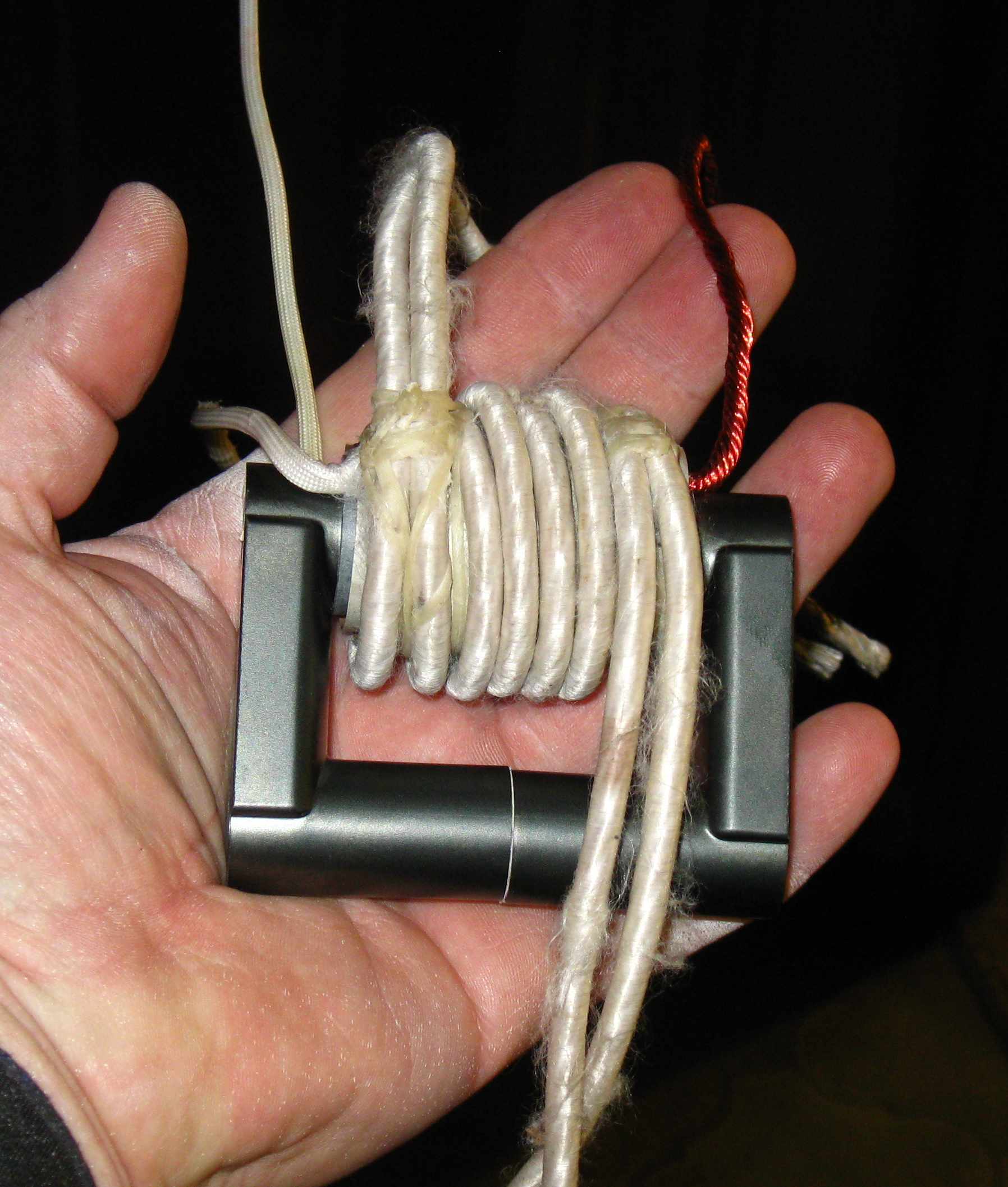
Current Transformer
![]()
![]() For experimental work, I recommend using a current transformer on one of the
transformer primary legs to monitor the current. The current should be
kept under about 40 amps peak. I use a PE-51687NL, Mouser
673-PE-51687NL 100 turn transformer. When shunted with a 10 ohm 5 watt
resistor, it provides 1 volt per 10 amps of current flow. The highest
primary current flows with small work coils that draw relatively low power
(few hundred watts) and with large objects that load the heater near its
maximum rating. I leave the CT on my transformer all the time and
scope it any time I'm doing something new.
For experimental work, I recommend using a current transformer on one of the
transformer primary legs to monitor the current. The current should be
kept under about 40 amps peak. I use a PE-51687NL, Mouser
673-PE-51687NL 100 turn transformer. When shunted with a 10 ohm 5 watt
resistor, it provides 1 volt per 10 amps of current flow. The highest
primary current flows with small work coils that draw relatively low power
(few hundred watts) and with large objects that load the heater near its
maximum rating. I leave the CT on my transformer all the time and
scope it any time I'm doing something new.
Availability
As with previous versions, parts kits, bare boards and assembled/tested heaters are available from Fluxeon. If you're interested in a general purpose, highly flexible heater with variable power output and computer control then you might want to wait on our commercial version, the 3.2 heater. Available sometime during 1Q2011.